HP 6125G HP 6125G & 6125G/XG Blade Switches IP Multicast Configuration - Page 290
Verifying the configuration, MLD SSM mapping configuration example, Network requirements
 |
View all HP 6125G manuals
Add to My Manuals
Save this manual to your list of manuals |
Page 290 highlights
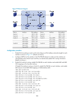
[SwitchB-Vlan-interface201] pim ipv6 dm [SwitchB-Vlan-interface201] quit # Enable IPv6 multicast routing on Switch C, enable IPv6 PIM-DM on each interface, and enable MLD on VLAN-interface 200. system-view [SwitchC] multicast ipv6 routing-enable [SwitchC] interface vlan-interface 200 [SwitchC-Vlan-interface200] mld enable [SwitchC-Vlan-interface200] pim ipv6 dm [SwitchC-Vlan-interface200] quit [SwitchC] interface vlan-interface 202 [SwitchC-Vlan-interface202] pim ipv6 dm [SwitchC-Vlan-interface202] quit 4. Configure an IPv6 multicast group filter on Switch A, so that the hosts connected to VLAN-interface 100 can join IPv6 multicast group FF1E::101 only. [SwitchA] acl ipv6 number 2001 [SwitchA-acl6-basic-2001] rule permit source ff1e::101 128 [SwitchA-acl6-basic-2001] quit [SwitchA] interface vlan-interface 100 [SwitchA-Vlan-interface100] mld group-policy 2001 [SwitchA-Vlan-interface100] quit Verifying the configuration # Display MLD information on VLAN-interface 200 of Switch B. [SwitchB] display mld interface vlan-interface 200 Vlan-interface200(FE80::200:5EFF:FE66:5100): MLD is enabled Current MLD version is 1 Value of query interval for MLD(in seconds): 125 Value of other querier present interval for MLD(in seconds): 255 Value of maximum query response time for MLD(in seconds): 10 Querier for MLD: FE80::200:5EFF:FE66:5100 (this router) Total 1 MLD Group reported MLD SSM mapping configuration example Network requirements As shown in Figure 79, the IPv6 PIM-SM domain applies both the ASM model and SSM model for IPv6 multicast delivery. Switch D's VLAN-interface 104 serves as the C-BSR and C-RP. The SSM group range is FF3E::/64. MLDv2 runs on Switch D's VLAN-interface 400. The receiver host runs MLDv1, and does not support MLDv2. Therefore, the Receiver host cannot specify expected multicast sources in its membership reports. Source 1, Source 2, and Source 3 send IPv6 multicast packets to multicast groups in the IPv6 SSM group range. You can configure the MLD SSM mapping feature on Switch D so that the receiver host will receive IPv6 multicast data from Source 1 and Source 3 only. 279
-
 1
1 -
2
-
3
-
4
-
5
-
6
-
7
-
8
-
9
-
10
-
11
-
12
-
13
-
14
-
15
-
16
-
17
-
18
-
19
-
20
-
21
-
22
-
23
-
24
-
25
-
26
-
27
-
28
-
29
-
30
-
31
-
32
-
33
-
34
-
35
-
36
-
37
-
38
-
39
-
40
-
41
-
42
-
43
-
44
-
45
-
46
-
47
-
48
-
49
-
50
-
51
-
52
-
53
-
54
-
55
-
56
-
57
-
58
-
59
-
60
-
61
-
62
-
63
-
64
-
65
-
66
-
67
-
68
-
69
-
70
-
71
-
72
-
73
-
74
-
75
-
76
-
77
-
78
-
79
-
80
-
81
-
82
-
83
-
84
-
85
-
86
-
87
-
88
-
89
-
90
-
91
-
92
-
93
-
94
-
95
-
96
-
97
-
98
-
99
-
100
-
101
-
102
-
103
-
104
-
105
-
106
-
107
-
108
-
109
-
110
-
111
-
112
-
113
-
114
-
115
-
116
-
117
-
118
-
119
-
120
-
121
-
122
-
123
-
124
-
125
-
126
-
127
-
128
-
129
-
130
-
131
-
132
-
133
-
134
-
135
-
136
-
137
-
138
-
139
-
140
-
141
-
142
-
143
-
144
-
145
-
146
-
147
-
148
-
149
-
150
-
151
-
152
-
153
-
154
-
155
-
156
-
157
-
158
-
159
-
160
-
161
-
162
-
163
-
164
-
165
-
166
-
167
-
168
-
169
-
170
-
171
-
172
-
173
-
174
-
175
-
176
-
177
-
178
-
179
-
180
-
181
-
182
-
183
-
184
-
185
-
186
-
187
-
188
-
189
-
190
-
191
-
192
-
193
-
194
-
195
-
196
-
197
-
198
-
199
-
200
-
201
-
202
-
203
-
204
-
205
-
206
-
207
-
208
-
209
-
210
-
211
-
212
-
213
-
214
-
215
-
216
-
217
-
218
-
219
-
220
-
221
-
222
-
223
-
224
-
225
-
226
-
227
-
228
-
229
-
230
-
231
-
232
-
233
-
234
-
235
-
236
-
237
-
238
-
239
-
240
-
241
-
242
-
243
-
244
-
245
-
246
-
247
-
248
-
249
-
250
-
251
-
252
-
253
-
254
-
255
-
256
-
257
-
258
-
259
-
260
-
261
-
262
-
263
-
264
-
265
-
266
-
267
-
268
-
269
-
270
-
271
-
272
-
273
-
274
-
275
-
276
-
277
-
278
-
279
-
280
-
281
-
282
-
283
-
284
-
 285
285 -
 286
286 -
 287
287 -
 288
288 -
 289
289 -
 290
290 -
 291
291 -
 292
292 -
 293
293 -
 294
294 -
 295
295 -
296
-
297
-
298
-
299
-
300
-
301
-
302
-
303
-
304
-
305
-
306
-
307
-
308
-
309
-
310
-
311
-
312
-
313
-
314
-
315
-
316
-
317
-
318
-
319
-
320
-
321
-
322
-
323
-
324
-
325
-
326
-
327
-
328
-
329
-
330
-
331
-
332
-
333
-
334
-
335
-
336
-
337
-
338
-
339
-
340
-
341
-
342
-
343
-
344
-
345
-
346
-
347
-
348
-
349
-
350
-
351
-
352
-
353
-
354
-
355
-
356
-
357
-
358
-
359
-
360
-
361
-
362
-
363
-
364
-
365
-
366
-
367
-
368
-
369
-
370
-
371
-
372
-
373
-
374
-
375
-
376
-
377
-
378
-
379
 |
 |