HP 8550dn HP Color LaserJet 8550, 8550N, 8550DN, 8550GN, 8550MFP Printer - Get - Page 15
To connect the interface cable, and power cords for a printer, with an optional tray 4
 |
UPC - 088698946428
View all HP 8550dn manuals
Add to My Manuals
Save this manual to your list of manuals |
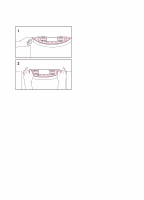
Page 15 highlights
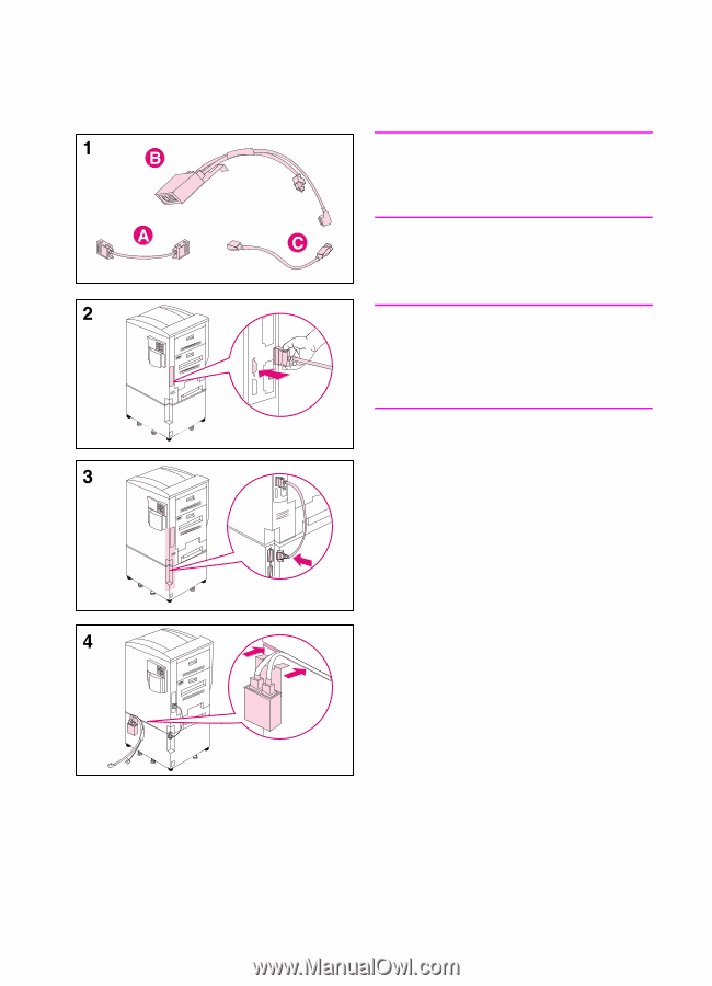
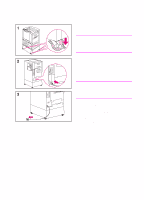
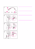
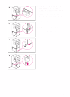
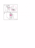
To connect the interface cable and power cords for a printer with an optional tray 4 Note Make sure that the printer is off (power button out) before attaching the interface cable and connecting the power cords. 1 Locate the interface cable (A), the power pack (B), and the straight power cord (C). Note The interface cable (A) might already be attached to the printer and tray 4. If it is, proceed to step 4 below; otherwise, continue with step 2. 2 Attach the end of the interface cable that is marked with one dot to the printer above the parallel connector. 3 Attach the other end of the interface cable (marked with two dots) to the connector on tray 4 that is marked with two dots. 4 Attach the power pack to the back of the printer by inserting the clip into the space between the printer and tray 4. EN Step 3: Installing the Cables 11
-
 1
1 -
2
-
3
-
4
-
5
-
6
-
7
-
8
-
9
-
 10
10 -
 11
11 -
 12
12 -
 13
13 -
 14
14 -
 15
15 -
 16
16 -
 17
17 -
 18
18 -
 19
19 -
 20
20 -
21
-
22
-
23
-
24
-
25
-
26
-
27
-
28
-
29
-
30
-
31
-
32
-
33
-
34
-
35
-
36
-
37
-
38
-
39
-
40
-
41
-
42
-
43
-
44
-
45
-
46
-
47
-
48
-
49
-
50
-
51
-
52
-
53
-
54
-
55
-
56
-
57
-
58
-
59
-
60
-
61
-
62
-
63
-
64
 |
 |