HP Cisco MDS 9020 Cisco MDS 9100 Series Hardware Installation Guide (OL-17951- - Page 24
Switch LEDs
 |
View all HP Cisco MDS 9020 manuals
Add to My Manuals
Save this manual to your list of manuals |
Page 24 highlights
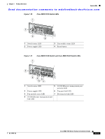
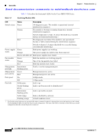
Switch LEDs Chapter 1 Product Overview Send documentation comments to [email protected] Only the first port in each four-port group can be an Inter-Switch Link (ISL). If the first port is an ISL, the other three ports in the group are disabled. See Figure 1-8. Figure 1-8 Cisco MDS 9140 and Cisco MDS 9120 Switch Ports 94180 12 3 4 1 Console port 3 Bandwidth optimized switching ports 2 10/100 Ethernet management port 4 Host-optimized switching port groups Switch LEDs The front panel of the Cisco MDS 9100 Series includes the LEDs shown in Figure 1-9, Figure 1-10, and Figure 1-11. You can use the LEDs on this panel to quickly identify system status. Figure 1-9 Cisco MDS 9134 Switch LEDs 1 2 3 5 4 1 Switch status LED 2 Power supply LED 3 Fan module status LED 184093 4 10/100 Ethernet management port link LED 5 10/100 Ethernet management port activity LED 1-10 Cisco MDS 9100 Series Hardware Installation Guide OL-17951-02
-
 1
1 -
2
-
3
-
4
-
5
-
6
-
7
-
8
-
9
-
10
-
11
-
12
-
13
-
14
-
15
-
16
-
17
-
18
-
 19
19 -
 20
20 -
 21
21 -
 22
22 -
 23
23 -
 24
24 -
 25
25 -
 26
26 -
 27
27 -
 28
28 -
 29
29 -
30
-
31
-
32
-
33
-
34
-
35
-
36
-
37
-
38
-
39
-
40
-
41
-
42
-
43
-
44
-
45
-
46
-
47
-
48
-
49
-
50
-
51
-
52
-
53
-
54
-
55
-
56
-
57
-
58
-
59
-
60
-
61
-
62
-
63
-
64
-
65
-
66
-
67
-
68
-
69
-
70
-
71
-
72
-
73
-
74
-
75
-
76
-
77
-
78
-
79
-
80
-
81
-
82
-
83
-
84
-
85
-
86
-
87
-
88
-
89
-
90
-
91
-
92
-
93
-
94
-
95
-
96
-
97
-
98
-
99
-
100
-
101
-
102
-
103
-
104
-
105
-
106
-
107
-
108
 |
 |
