HP Cisco MDS 9020 Cisco MDS 9100 Series Hardware Installation Guide (OL-17951- - Page 54
Removing and Installing Components
 |
View all HP Cisco MDS 9020 manuals
Add to My Manuals
Save this manual to your list of manuals |
Page 54 highlights
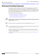
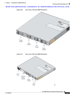
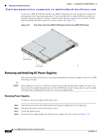
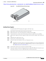
Removing and Installing Components Chapter 2 Installing the Cisco MDS 9100 Series Send documentation comments to [email protected] Removing and Installing Components The Cisco MDS 9140 Switch and the Cisco MDS 9120 Switch is shipped with two field-replaceable power supplies. Each power supply includes a fixed fan. The Cisco MDS 9140 Switch and the Cisco MDS 9120 Switch also have two field-replaceable fan modules. The Cisco MDS 9134 Switch has two hot-swappable power supplies and two hot-swappable fan modules. The Cisco MDS 9124 Switch is shipped with one field-replaceable power supply and three fixed fans. The Cisco MDS 9100 Series switches support the new DC power supply. This section provides the following information: • Removing and Installing AC Power Supplies, page 2-28 • Removing and Installing DC Power Supplies, page 2-30 • Removing and Installing Fan Modules, page 2-32 Warning Hazardous voltage or energy is present on the backplane when the system is operating. Use caution when servicing. Statement 1034 Caution During this procedure, wear grounding wrist straps to avoid ESD damage to the switch. Note The Cisco MDS 9100 Series switch is only supported for operation with both power supplies and both fan modules installed, and with all fans working. With two power supplies installed, if one power supply fails, the system can continue to function normally on a single healthy power supply. However, the failed power supply should be replaced as soon as possible to provide redundancy. The fan modules are required to ensure proper cooling of the switches. See Figure 2-20, Figure 2-21, and Figure 2-22. 2-26 Cisco MDS 9100 Series Hardware Installation Guide OL-17951-02
-
 1
1 -
2
-
3
-
4
-
5
-
6
-
7
-
8
-
9
-
10
-
11
-
12
-
13
-
14
-
15
-
16
-
17
-
18
-
19
-
20
-
21
-
22
-
23
-
24
-
25
-
26
-
27
-
28
-
29
-
30
-
31
-
32
-
33
-
34
-
35
-
36
-
37
-
38
-
39
-
40
-
41
-
42
-
43
-
44
-
45
-
46
-
47
-
48
-
 49
49 -
 50
50 -
 51
51 -
 52
52 -
 53
53 -
 54
54 -
 55
55 -
 56
56 -
 57
57 -
 58
58 -
 59
59 -
60
-
61
-
62
-
63
-
64
-
65
-
66
-
67
-
68
-
69
-
70
-
71
-
72
-
73
-
74
-
75
-
76
-
77
-
78
-
79
-
80
-
81
-
82
-
83
-
84
-
85
-
86
-
87
-
88
-
89
-
90
-
91
-
92
-
93
-
94
-
95
-
96
-
97
-
98
-
99
-
100
-
101
-
102
-
103
-
104
-
105
-
106
-
107
-
108
 |
 |
