HP Cisco MDS 9020 Cisco MDS 9100 Series Hardware Installation Guide (OL-17951- - Page 59
Installing Power Supplies, Step 1
 |
View all HP Cisco MDS 9020 manuals
Add to My Manuals
Save this manual to your list of manuals |
Page 59 highlights
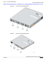
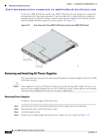
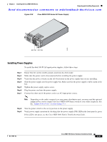
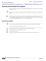
Chapter 2 Installing the Cisco MDS 9100 Series Removing and Installing Components Send documentation comments to [email protected] Figure 2-24 Cisco MDS 9100 Series DC Power Supply DC input terminals Handle 120697 Status LEDs Installing Power Supplies To install the 300-W DC-input power supplies, follow these steps: Step 1 Step 2 Step 3 Step 4 Step 5 Ensure that the system (earth) ground connection has been made. Slide the power supply into the power supply bay. Make sure that the power supply is fully seated in the bay. The input LED is green and indicates an OK condition, but the output LED is red. Switch off the DC power source and switch it on again. Ensure that the output LED is green. The switch can now receive the down converted 12 VDC from the inserted DC power supply. Tighten the power supply captive screw. Note Depending on the outlet receptacle on your power distribution unit, you may need the optional jumper power cord to connect the Cisco MDS 9100 Series switch to your outlet receptacle. See the "Jumper Power Cord" section on page C-5. Step 6 Verify power supply operation by checking that the power supply (P/S) LED in the front panel is green. If the LED is not green, see the Cisco MDS 9000 Family Troubleshooting Guide. OL-17951-02 Cisco MDS 9100 Series Hardware Installation Guide 2-31
-
 1
1 -
2
-
3
-
4
-
5
-
6
-
7
-
8
-
9
-
10
-
11
-
12
-
13
-
14
-
15
-
16
-
17
-
18
-
19
-
20
-
21
-
22
-
23
-
24
-
25
-
26
-
27
-
28
-
29
-
30
-
31
-
32
-
33
-
34
-
35
-
36
-
37
-
38
-
39
-
40
-
41
-
42
-
43
-
44
-
45
-
46
-
47
-
48
-
49
-
50
-
51
-
52
-
53
-
 54
54 -
 55
55 -
 56
56 -
 57
57 -
 58
58 -
 59
59 -
 60
60 -
 61
61 -
 62
62 -
 63
63 -
 64
64 -
65
-
66
-
67
-
68
-
69
-
70
-
71
-
72
-
73
-
74
-
75
-
76
-
77
-
78
-
79
-
80
-
81
-
82
-
83
-
84
-
85
-
86
-
87
-
88
-
89
-
90
-
91
-
92
-
93
-
94
-
95
-
96
-
97
-
98
-
99
-
100
-
101
-
102
-
103
-
104
-
105
-
106
-
107
-
108
 |
 |
