HP Cisco MDS 9020 Cisco MDS 9100 Series Hardware Installation Guide (OL-17951- - Page 44
Sliding the Cisco MDS 9100 Series Switch Rear-Facing onto the Slider Rails, Step 2
 |
View all HP Cisco MDS 9020 manuals
Add to My Manuals
Save this manual to your list of manuals |
Page 44 highlights
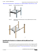
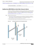
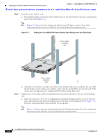
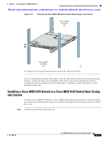
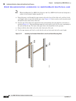
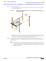
Installing the Switch in a Cabinet with Insufficient Front Clearance Chapter 2 Installing the Cisco MDS 9100 Series Send documentation comments to [email protected] Step 2 Insert the switch into the rack: a. By using both hands, position the switch with the back of the switch between the rear rack-mounting rails as shown in Figure 2-11. Note Figure 2-11 shows the front rack-mount brackets in a 180 degree position. Your front rack-mount brackets may look different if you kept them in the normal position. Figure 2-11 Sliding the Cisco MDS 9100 Series Switch (Rear-Facing) onto the Slider Rails Front cabinet mounting rails 113429 Rear cabinet mounting rails Step 3 b. Align the two C brackets on either side of the switch with the slider rails installed in the rack. Slide the C brackets onto the slider rails and then gently slide the switch all the way into the rack. If the switch does not slide easily, try realigning the C brackets on the slider rails. Stabilize the switch in the rack by attaching the front rack-mount brackets to the rear rack-mounting rails: a. Insert two screws (12-24 or 10-32, depending on rack type) through the holes in one of the front rack-mount brackets and into the threaded holes in the back rack-mounting rail (see Figure 2-12.) For racks with square holes, first install the 12-24 cage nuts. Note Figure 2-12 shows the front rack-mount brackets in 180 degree position. Your front rack-mount brackets may look different if you kept them in the normal position. 2-16 Cisco MDS 9100 Series Hardware Installation Guide OL-17951-02
-
 1
1 -
2
-
3
-
4
-
5
-
6
-
7
-
8
-
9
-
10
-
11
-
12
-
13
-
14
-
15
-
16
-
17
-
18
-
19
-
20
-
21
-
22
-
23
-
24
-
25
-
26
-
27
-
28
-
29
-
30
-
31
-
32
-
33
-
34
-
35
-
36
-
37
-
38
-
 39
39 -
 40
40 -
 41
41 -
 42
42 -
 43
43 -
 44
44 -
 45
45 -
 46
46 -
 47
47 -
 48
48 -
 49
49 -
50
-
51
-
52
-
53
-
54
-
55
-
56
-
57
-
58
-
59
-
60
-
61
-
62
-
63
-
64
-
65
-
66
-
67
-
68
-
69
-
70
-
71
-
72
-
73
-
74
-
75
-
76
-
77
-
78
-
79
-
80
-
81
-
82
-
83
-
84
-
85
-
86
-
87
-
88
-
89
-
90
-
91
-
92
-
93
-
94
-
95
-
96
-
97
-
98
-
99
-
100
-
101
-
102
-
103
-
104
-
105
-
106
-
107
-
108
 |
 |
