HP DL580 ProLiant DL580 Generation 4 Maintenance and Service Guide - Page 79
Memory board components and LEDs
 |
UPC - 882780616011
View all HP DL580 manuals
Add to My Manuals
Save this manual to your list of manuals |
Page 79 highlights
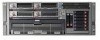
Memory board components and LEDs Error indicators remain illuminated when the system is powered off so that the status of the LEDs can still be seen. This behavior matches the behavior of all the other error indicators in the server. The indicators are only cleared in the following situations: • If the locking switch is locked after the board is reinstalled • If the server is rebooted • If the board is removed from the server CAUTION: When the memory board locking switch is unlocked in a mode that does not support hot-add or hot-replace capabilities, audio alarms and visual alerts occur. Removing the memory board at this point causes server failure. To end the audio alarms and visual alerts, move the memory board locking switch back to the locked position. This action does not result in data corruption or server failure. If removal of a single memory board is required and it is the only memory board, power down the server and make the necessary memory changes. Item 1 2 3 4 Description Locking switch Release latch Ejector lever Removable 5 DIMM LEDs (1-4) Status N/A N/A N/A Off = Do not remove memory board if server is powered on Green = Memory board can be safely removed Off = Normal or DIMM not installed Amber = Uncorrectable error detected or correctable error threshold reached Flashing amber = DIMM configuration error Server component identification 79
-
 1
1 -
2
-
3
-
4
-
5
-
6
-
7
-
8
-
9
-
10
-
11
-
12
-
13
-
14
-
15
-
16
-
17
-
18
-
19
-
20
-
21
-
22
-
23
-
24
-
25
-
26
-
27
-
28
-
29
-
30
-
31
-
32
-
33
-
34
-
35
-
36
-
37
-
38
-
39
-
40
-
41
-
42
-
43
-
44
-
45
-
46
-
47
-
48
-
49
-
50
-
51
-
52
-
53
-
54
-
55
-
56
-
57
-
58
-
59
-
60
-
61
-
62
-
63
-
64
-
65
-
66
-
67
-
68
-
69
-
70
-
71
-
72
-
73
-
 74
74 -
 75
75 -
 76
76 -
 77
77 -
 78
78 -
 79
79 -
 80
80 -
 81
81 -
 82
82 -
 83
83 -
 84
84 -
85
-
86
-
87
-
88
-
89
-
90
-
91
-
92
-
93
-
94
-
95
-
96
-
97
-
98
-
99
-
100
-
101
-
102
-
103
-
104
-
105
-
106
-
107
-
108
-
109
 |
 |
