HP EliteBook 2760p HP EliteBook 2760p Tablet PC - Maintenance and Service Gui - Page 24
Bottom - dock
 |
View all HP EliteBook 2760p manuals
Add to My Manuals
Save this manual to your list of manuals |
Page 24 highlights
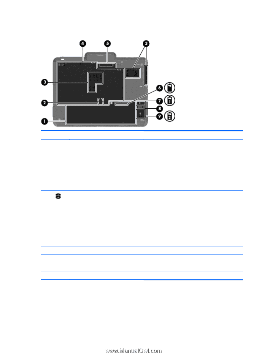
Bottom Component (1) (2) Battery bay SIM slot (3) Vents (3) (4) Hard drive bay (5) Docking connector (6) Charge level indicator (7) Battery release latch (8) Accessory battery connector (9) Accessory battery connector door Description Holds the battery. Supports a wireless subscriber identity module (SIM). The SIM slot is located inside the battery bay. Enable airflow to cool internal components. NOTE: The computer fan starts up automatically to cool internal components and prevent overheating. It is normal for the internal fan to cycle on and off during routine operation. Contains the hard drive, the wireless LAN module slot, the WWAN module slot, and the memory module slot. CAUTION: To prevent an unresponsive system, replace the wireless module only with a wireless module authorized for use in the computer by the governmental agency that regulates wireless devices in your country or region. If you replace the module and then receive a warning message, remove the module to restore computer functionality, and then contact technical support through Help and Support. Connects an optional docking device. Displays the approximate remaining battery charge. Releases the battery from the battery bay. Connects an optional accessory battery. Slides open to expose the accessory battery connector. 16 Chapter 2 External component identification
-
 1
1 -
2
-
3
-
4
-
5
-
6
-
7
-
8
-
9
-
10
-
11
-
12
-
13
-
14
-
15
-
16
-
17
-
18
-
 19
19 -
 20
20 -
 21
21 -
 22
22 -
 23
23 -
 24
24 -
 25
25 -
 26
26 -
 27
27 -
 28
28 -
 29
29 -
30
-
31
-
32
-
33
-
34
-
35
-
36
-
37
-
38
-
39
-
40
-
41
-
42
-
43
-
44
-
45
-
46
-
47
-
48
-
49
-
50
-
51
-
52
-
53
-
54
-
55
-
56
-
57
-
58
-
59
-
60
-
61
-
62
-
63
-
64
-
65
-
66
-
67
-
68
-
69
-
70
-
71
-
72
-
73
-
74
-
75
-
76
-
77
-
78
-
79
-
80
-
81
-
82
-
83
-
84
-
85
-
86
-
87
-
88
-
89
-
90
-
91
-
92
-
93
-
94
-
95
-
96
-
97
-
98
-
99
-
100
-
101
-
102
-
103
-
104
-
105
-
106
-
107
-
108
-
109
-
110
-
111
-
112
-
113
-
114
-
115
 |
 |