HP EliteBook 2760p HP EliteBook 2760p Tablet PC - Maintenance and Service Gui - Page 87
Position the system board right side up., Remove the fan/heat sink assembly
 |
View all HP EliteBook 2760p manuals
Add to My Manuals
Save this manual to your list of manuals |
Page 87 highlights
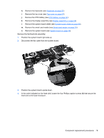
h. Remove the keyboard (see Keyboard on page 53) i. Remove the top cover (see Top cover on page 57) j. Remove the RTC battery (see RTC battery on page 62) k. Remove the display assembly (see Display assembly on page 63) l. Remove the system board shield (see System board shield on page 66) m. Remove the smart card reader (see Smart card reader on page 74) n. Remove the system board (see System board on page 76) Remove the fan/heat sink assembly: 1. Position the system board right side up. 2. Disconnect the fan cable from the system board. 3. Position the system board upside down. 4. In the order indicated on the heat sink, loosen the four Phillips captive screws (1) that secure the heat sink to the base enclosure. Component replacement procedures 79
-
 1
1 -
2
-
3
-
4
-
5
-
6
-
7
-
8
-
9
-
10
-
11
-
12
-
13
-
14
-
15
-
16
-
17
-
18
-
19
-
20
-
21
-
22
-
23
-
24
-
25
-
26
-
27
-
28
-
29
-
30
-
31
-
32
-
33
-
34
-
35
-
36
-
37
-
38
-
39
-
40
-
41
-
42
-
43
-
44
-
45
-
46
-
47
-
48
-
49
-
50
-
51
-
52
-
53
-
54
-
55
-
56
-
57
-
58
-
59
-
60
-
61
-
62
-
63
-
64
-
65
-
66
-
67
-
68
-
69
-
70
-
71
-
72
-
73
-
74
-
75
-
76
-
77
-
78
-
79
-
80
-
81
-
 82
82 -
 83
83 -
 84
84 -
 85
85 -
 86
86 -
 87
87 -
 88
88 -
 89
89 -
 90
90 -
 91
91 -
 92
92 -
93
-
94
-
95
-
96
-
97
-
98
-
99
-
100
-
101
-
102
-
103
-
104
-
105
-
106
-
107
-
108
-
109
-
110
-
111
-
112
-
113
-
114
-
115
 |
 |
