HP LaserJet Pro 300 Service Manual - Page 118
WARNING, Before you proceed
 |
View all HP LaserJet Pro 300 manuals
Add to My Manuals
Save this manual to your list of manuals |
Page 118 highlights
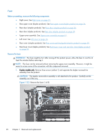
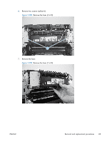
4. Before you proceed, look at Figure 1-136 Remove the fuser (4 of 8) on page 94. In the following step, the connector and guide will be separated from the fuser. You must not use too much force and damage the lower portion of the guide. If the guide is damaged, the fuser must be replaced. Figure 1-136 Remove the fuser (4 of 8) 5. Carefully disconnect one connector and rotate the connector and the top portion of the guide away from the fuser (callout 1). WARNING! Do not separate the connector and guide more than is shown in Figure 1-136 Remove the fuser (4 of 8) on page 94. If the guide is damaged, you must replace the fuser. Figure 1-137 Remove the fuser (5 of 8) 1 94 Chapter 1 Removal and replacement ENWW
-
 1
1 -
2
-
3
-
4
-
5
-
6
-
7
-
8
-
9
-
10
-
11
-
12
-
13
-
14
-
15
-
16
-
17
-
18
-
19
-
20
-
21
-
22
-
23
-
24
-
25
-
26
-
27
-
28
-
29
-
30
-
31
-
32
-
33
-
34
-
35
-
36
-
37
-
38
-
39
-
40
-
41
-
42
-
43
-
44
-
45
-
46
-
47
-
48
-
49
-
50
-
51
-
52
-
53
-
54
-
55
-
56
-
57
-
58
-
59
-
60
-
61
-
62
-
63
-
64
-
65
-
66
-
67
-
68
-
69
-
70
-
71
-
72
-
73
-
74
-
75
-
76
-
77
-
78
-
79
-
80
-
81
-
82
-
83
-
84
-
85
-
86
-
87
-
88
-
89
-
90
-
91
-
92
-
93
-
94
-
95
-
96
-
97
-
98
-
99
-
100
-
101
-
102
-
103
-
104
-
105
-
106
-
107
-
108
-
109
-
110
-
111
-
112
-
 113
113 -
 114
114 -
 115
115 -
 116
116 -
 117
117 -
 118
118 -
 119
119 -
 120
120 -
 121
121 -
 122
122 -
 123
123 -
124
-
125
-
126
-
127
-
128
-
129
-
130
-
131
-
132
-
133
-
134
-
135
-
136
-
137
-
138
-
139
-
140
-
141
-
142
-
143
-
144
-
145
-
146
-
147
-
148
-
149
-
150
-
151
-
152
-
153
-
154
-
155
-
156
-
157
-
158
-
159
-
160
-
161
-
162
-
163
-
164
-
165
-
166
-
167
-
168
-
169
-
170
-
171
-
172
-
173
-
174
-
175
-
176
-
177
-
178
-
179
-
180
-
181
-
182
-
183
-
184
-
185
-
186
-
187
-
188
-
189
-
190
-
191
-
192
-
193
-
194
-
195
-
196
-
197
-
198
-
199
-
200
-
201
-
202
-
203
-
204
-
205
-
206
-
207
-
208
-
209
-
210
-
211
-
212
-
213
-
214
-
215
-
216
-
217
-
218
-
219
-
220
-
221
-
222
-
223
-
224
-
225
-
226
-
227
-
228
-
229
-
230
-
231
-
232
-
233
-
234
-
235
-
236
-
237
-
238
-
239
-
240
-
241
-
242
-
243
-
244
-
245
-
246
-
247
-
248
-
249
-
250
-
251
-
252
-
253
-
254
-
255
-
256
-
257
-
258
-
259
-
260
-
261
-
262
-
263
-
264
-
265
-
266
-
267
-
268
-
269
-
270
 |
 |

4.
Before you proceed
, look at
Figure
1
-
136
Remove the fuser (4 of 8)
on page
94
. In the
following step, the connector and guide will be separated from the fuser. You
must not
use too
much force and damage the lower portion of the guide. If the guide is damaged, the fuser must be
replaced.
Figure 1-136
Remove the fuser (4 of 8)
5.
Carefully disconnect one connector and rotate the connector and the top portion of the guide
away from the fuser (callout 1).
WARNING!
Do not separate the connector and guide more than is shown in
Figure
1
-
136
Remove the fuser (4 of 8)
on page
94
. If the guide is damaged, you must replace the fuser.
Figure 1-137
Remove the fuser (5 of 8)
1
94
Chapter 1
Removal and replacement
ENWW