HP Pavilion dv3000 HP Pavilion dv3000 Entertainment PC - Maintenance and Servi
HP Pavilion dv3000 - Entertainment Notebook PC Manual
 |
View all HP Pavilion dv3000 manuals
Add to My Manuals
Save this manual to your list of manuals |
HP Pavilion dv3000 manual content summary:
- HP Pavilion dv3000 | HP Pavilion dv3000 Entertainment PC - Maintenance and Servi - Page 1
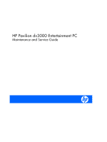
HP Pavilion dv3000 Entertainment PC Maintenance and Service Guide - HP Pavilion dv3000 | HP Pavilion dv3000 Entertainment PC - Maintenance and Servi - Page 2
States and other countries. Microsoft, Windows, and Windows Vista are either trademarks or registered trademarks services. Nothing herein should be construed as constituting an additional warranty. HP shall not be liable for technical or editorial errors or omissions contained herein. First Edition - HP Pavilion dv3000 | HP Pavilion dv3000 Entertainment PC - Maintenance and Servi - Page 3
, such as an adjoining optional printer, or a soft surface, such as pillows or rugs or clothing, to block airflow. Also, do not allow the AC adapter to contact the skin or a soft surface, such as pillows or rugs or clothing, during operation. The computer and the AC - HP Pavilion dv3000 | HP Pavilion dv3000 Entertainment PC - Maintenance and Servi - Page 4
iv Safety warning notice - HP Pavilion dv3000 | HP Pavilion dv3000 Entertainment PC - Maintenance and Servi - Page 5
19 Mass storage devices ...20 Miscellaneous parts ...21 Sequential part number listing 22 4 Removal and replacement procedures Preliminary replacement requirements 25 Tools required ...25 Service considerations 25 Plastic parts 25 Cables and connectors 26 Drive handling 26 Grounding guidelines - HP Pavilion dv3000 | HP Pavilion dv3000 Entertainment PC - Maintenance and Servi - Page 6
Workstation guidelines 28 Equipment guidelines 29 Unknown user password 30 Component replacement procedures 31 Serial number ...31 Computer feet ...32 Battery ...32 WLAN module ...34 Optical drive ...37 Memory module ...38 Hard drive ...40 Keyboard ...42 Switch cover ...44 Top cover ...45 - HP Pavilion dv3000 | HP Pavilion dv3000 Entertainment PC - Maintenance and Servi - Page 7
hard drive 105 Updating reinstalled software 105 9 Connector pin assignments Audio-out (headphone) ...106 Audio-in (microphone) ...106 External monitor ...107 RJ-11 (modem) ...108 RJ-45 (network) ...108 Universal Serial Bus ...109 10 Power - HP Pavilion dv3000 | HP Pavilion dv3000 Entertainment PC - Maintenance and Servi - Page 8
11 Recycling Battery ...112 Display ...112 Index ...118 viii - HP Pavilion dv3000 | HP Pavilion dv3000 Entertainment PC - Maintenance and Servi - Page 9
Processors Chipset Graphics Panel Memory Hard drives Description HP Pavilion dv3000 Entertainment PC Intel® Core™ 2 Duo processors T9500 2. 2 SODIMM slots Customer-accessible/upgradable Supports up to 4 GB of system RAM Support for DDRII dual-channel 667- and 800-MHz Support for: ● 4096 MB (2048 - HP Pavilion dv3000 | HP Pavilion dv3000 Entertainment PC - Maintenance and Servi - Page 10
(MMC), Memory Stick (MS), Memory Stick Pro (MSP), xD-Picture Card (XD) Support for miniature versions of SD, MMC, MS Duo with adapter (adapter is not included) Audio-in (mono microphone) Audio-out (stereo headphone) (2) Consumer infrared Extended serial advanced technology (eSATA) 2 Chapter - HP Pavilion dv3000 | HP Pavilion dv3000 Entertainment PC - Maintenance and Servi - Page 11
cable slot Fingerprint reader with Digital Persona software support Preinstalled: Configurable Windows® Vista® with embedded QuickPlay Direct Windows Vista Ultimate (64-bit) Windows Vista Premium (32-bit) End-user replaceable parts: AC adapter Battery (system) Hard drive Memory module Optical drive - HP Pavilion dv3000 | HP Pavilion dv3000 Entertainment PC - Maintenance and Servi - Page 12
2 External component identification Top components Display components Item (1) Component Wireless antennae (2 or 3)* (2) Internal microphones (2) 4 Chapter 2 External component identification Function On select computer models, at least 2 antennae send and receive signals from one or more - HP Pavilion dv3000 | HP Pavilion dv3000 Entertainment PC - Maintenance and Servi - Page 13
video. ● Includes streaming video options and special effects for adding frames, filters, and emoticons in Help and Support. Buttons and fingerprint reader Item (1) Component Power button* Function responding and Windows® shutdown procedures are ineffective, press and hold the power button for - HP Pavilion dv3000 | HP Pavilion dv3000 Entertainment PC - Maintenance and Servi - Page 14
on to Windows. QuickPlay or DVDPlay launches after you log on. Refer to the QuickPlay or DVDPlay software Help for more Windows, instead of a password logon. *This table describes factory settings. For information about changing factory settings, refer to the user guides located in Help and Support - HP Pavilion dv3000 | HP Pavilion dv3000 Entertainment PC - Maintenance and Servi - Page 15
combination with the fn key. Executes frequently used system functions when pressed in combination with a function key or the esc key. Displays the Windows Start menu. Displays a shortcut menu for items beneath the pointer. Can be used like the keys on an external numeric keypad. Execute frequently - HP Pavilion dv3000 | HP Pavilion dv3000 Entertainment PC - Maintenance and Servi - Page 16
Lights Item (1) (2) Component Caps lock light Power lights (2)* (3) QuickPlay light (4) Volume mute light (5) Volume : An integrated wireless device, such as a wireless local area network (WLAN) device, the HP Broadband Wireless Module, and/or a Bluetooth® device, is on. ● Off: All wireless - HP Pavilion dv3000 | HP Pavilion dv3000 Entertainment PC - Maintenance and Servi - Page 17
If the computer is not plugged into an external power source, the light stays off until the battery reaches a low battery level. *The 2 power lights display the same information. The light on the power button is visible only when the computer is open. The power light on the front of the computer is - HP Pavilion dv3000 | HP Pavilion dv3000 Entertainment PC - Maintenance and Servi - Page 18
sound when connected to optional powered stereo speakers, headphones, ear buds, a headset, or television audio. Receives a signal from the HP Remote Control (select models only . ● Off: The computer is off or in Hibernation. Connects an AC adapter. 10 Chapter 2 External component identification - HP Pavilion dv3000 | HP Pavilion dv3000 Entertainment PC - Maintenance and Servi - Page 19
, such as a highdefinition television, or any compatible digital or audio component. NOTE: Depending on your computer model, the computer may include an HDMI port or a USB port at this location. Supports the following optional digital card formats: Secure Digital (SD) Memory Card, MultiMediaCard - HP Pavilion dv3000 | HP Pavilion dv3000 Entertainment PC - Maintenance and Servi - Page 20
compartment Vents (5) Hard drive bay Optical drive release latch Wireless module compartment (select models only) Function Release the battery from the battery bay. Holds the battery. Contains the memory module slots. Enable airflow to cool internal components. NOTE: The computer fan starts up - HP Pavilion dv3000 | HP Pavilion dv3000 Entertainment PC - Maintenance and Servi - Page 21
3 Illustrated parts catalog Serial number location When ordering parts or requesting information, provide the computer serial number and model number located on the bottom of the computer. Serial number location 13 - HP Pavilion dv3000 | HP Pavilion dv3000 Entertainment PC - Maintenance and Servi - Page 22
Computer major components 14 Chapter 3 Illustrated parts catalog - HP Pavilion dv3000 | HP Pavilion dv3000 Entertainment PC - Maintenance and Servi - Page 23
drive cover (6) Fingerprint reader board (includes fingerprint reader board bracket, not illustrated) (7) System board (includes replacement thermal material and power connector cable) (8) RTC battery (includes double-sided tape) 468831-001 468499-001 468824-001 (9) Modem modules NOTE: The modem - HP Pavilion dv3000 | HP Pavilion dv3000 Entertainment PC - Maintenance and Servi - Page 24
Intel Core Duo T5550 1.83-GHz processor (2-MB of L2 cache, 667-MHz FSB) 458247-001 (13) Fan 468830-001 (14) Speakers 468828-001 (15) Batteries 6-cell, 2.55-Ah, 55-Wh Li-ion 468816-001 4-cell, 2.55-Ah, 37-Wh Li-ion 468815-001 (16) Base enclosure (includes 4 base rubber feet - HP Pavilion dv3000 | HP Pavilion dv3000 Entertainment PC - Maintenance and Servi - Page 25
Item Description ● For use in Japan Spare part number 441082-291 Intel 3945 802.11a/b/g WLAN modules: ● For use in Antigua and Barbuda, Argentina, Aruba, the Bahamas, Barbados, Bermuda, 451861-001 Brunei, Canada, the Cayman Islands, Chile, Colombia, Costa Rica, the Dominican Republic, Ecuador, El - HP Pavilion dv3000 | HP Pavilion dv3000 Entertainment PC - Maintenance and Servi - Page 26
Display assembly components Item Description Spare part number (1) Display bezel 468797-001 (2) Camera/microphone module 468804-001 (3) Display Hinge Kit (includes left and right display hinges) 468799-001 (4) Display inverter (includes Mylar shield) 468798-001 (5) 13.3-inch, WXGA - HP Pavilion dv3000 | HP Pavilion dv3000 Entertainment PC - Maintenance and Servi - Page 27
Plastics Kit Item Description Plastics Kit (1) ExpressCard slot bezel (2) Wireless module compartment cover (includes 1 captive screw, secured by a C-clip) (3) Memory module compartment cover (includes 2 captive screws, secured by C-clips) (4) Hard drive bay cover (includes 2 captive screws, - HP Pavilion dv3000 | HP Pavilion dv3000 Entertainment PC - Maintenance and Servi - Page 28
Mass storage devices Item Description (1) Hard drives (include bracket) 320-GB, 5400-rpm 250-GB, 5400-rpm 160-GB, 5400-rpm 120-GB, 5400-rpm Hard Drive Kit (not illustrated, includes hard drive bracket and screws) (2) Optical drives (include bezel and bracket) DVD±RW and CD-RW Super Multi, Double- - HP Pavilion dv3000 | HP Pavilion dv3000 Entertainment PC - Maintenance and Servi - Page 29
Miscellaneous parts Description 90-W PFC HP Smart Adapter Remote control (fits inside ExpressCard slot) Power cords: For use in Australia and New Zealand For use in India For use in Japan For use in the People's Republic of China For - HP Pavilion dv3000 | HP Pavilion dv3000 Entertainment PC - Maintenance and Servi - Page 30
for use in the United Kingdom 383496-291 Power cord for use in Japan 383496-AA1 Power cord for use in the People's Republic of China 383496-AB1 Power cord for use in Taiwan 383496-AD1 Power cord for use in South Korea 383496-D61 Power cord for use in India 398393-002 Bluetooth module - HP Pavilion dv3000 | HP Pavilion dv3000 Entertainment PC - Maintenance and Servi - Page 31
processor (2-MB of L2 cache, 800-MHz FSB) 463955-001 90-W PFC HP Smart Aapter 465539-001 Remote control (fits inside ExpressCard slot) 468499-001 System board (includes replacement thermal material and power connector cable) 468796-001 13.3-inch, WXGA BrightView display panel (includes display - HP Pavilion dv3000 | HP Pavilion dv3000 Entertainment PC - Maintenance and Servi - Page 32
-001 Rubber Foot Kit (includes 4 base enclosure rubber feet) 468824-001 RTC battery (includes double-sided tape) 468825-001 Modem module for use in all countries -001 Heat sink (includes heat sink retention clip and replacement thermal material) 468830-001 Fan 468831-001 Fingerprint reader board - HP Pavilion dv3000 | HP Pavilion dv3000 Entertainment PC - Maintenance and Servi - Page 33
to complete the removal and replacement procedures: ● Flat-bladed screwdriver ● Magnetic screwdriver ● Phillips P0 and P1 screwdrivers Service considerations The following sections include only at the points designated in the maintenance instructions. Preliminary replacement requirements 25 - HP Pavilion dv3000 | HP Pavilion dv3000 Entertainment PC - Maintenance and Servi - Page 34
Cables and connectors CAUTION: When servicing the computer, be sure that cables are placed in are routed in such a way that they cannot be caught or snagged by parts being removed or replaced. Handle flex cables with extreme care; these cables tear easily. Drive handling CAUTION: Drives are fragile - HP Pavilion dv3000 | HP Pavilion dv3000 Entertainment PC - Maintenance and Servi - Page 35
integrated circuits provide some protection, but in many cases, ESD contains enough power to alter device parameters or melt silicon junctions. A discharge of static V 21,000 V 11,000 V 55% 7,500 V 3,000 V 400 V 400 V 2,000 V 3,500 V 7,000 V 5,000 V Preliminary replacement requirements 27 - HP Pavilion dv3000 | HP Pavilion dv3000 Entertainment PC - Maintenance and Servi - Page 36
work surface and use properly grounded tools and equipment. ● Use conductive field service tools, such as cutters, screwdrivers, and vacuums. ● When fixtures must with pins, leads, or circuitry. ● Turn off power and input signals before inserting or removing connectors or test equipment. 28 Chapter 4 - HP Pavilion dv3000 | HP Pavilion dv3000 Entertainment PC - Maintenance and Servi - Page 37
resistance ● Static-dissipative tables or floor mats with hard ties to the ground ● Field service kits ● Static awareness labels ● Material-handling packages ● Nonconductive plastic bags, tubes, or Floor mats Voltage protection level 1,500 V 7,500 V 5,000 V Preliminary replacement requirements 29 - HP Pavilion dv3000 | HP Pavilion dv3000 Entertainment PC - Maintenance and Servi - Page 38
If the computer you are servicing has an unknown user adapter from the computer. 4. Remove the battery (see Battery on page 32). 5. Remove the RTC battery (see RTC battery on page 64). 6. Wait approximately 5 minutes. 7. Replace the RTC battery and reassemble the computer. 8. Connect AC power - HP Pavilion dv3000 | HP Pavilion dv3000 Entertainment PC - Maintenance and Servi - Page 39
, in 10 different sizes, that must be removed, replaced, or loosened when servicing the computer. Make special note of each screw size and location during removal and replacement. Serial number Report the computer serial number to HP when requesting information or ordering spare parts. The serial - HP Pavilion dv3000 | HP Pavilion dv3000 Entertainment PC - Maintenance and Servi - Page 40
system. 2. Disconnect all external devices connected to the computer. 3. Disconnect the power from the computer by first unplugging the power cord from the AC outlet and then unplugging the AC adapter from the computer. Remove the battery: 1. Turn the computer upside down on a flat surface with the - HP Pavilion dv3000 | HP Pavilion dv3000 Entertainment PC - Maintenance and Servi - Page 41
of the battery (1) into the battery bay and slide it forward until the battery is seated. Lock the battery into the battery bay by sliding the right battery release latch (2) to the left. The left battery release latch automatically locks the battery into place. Component replacement procedures 33 - HP Pavilion dv3000 | HP Pavilion dv3000 Entertainment PC - Maintenance and Servi - Page 42
● For use in Australia, New Zealand, Pakistan, and the People's Republic of China 451861-003 ● For use in Japan 451861-291 34 Chapter 4 Removal and replacement procedures - HP Pavilion dv3000 | HP Pavilion dv3000 Entertainment PC - Maintenance and Servi - Page 43
the computer by first unplugging the power cord from the AC outlet and then unplugging the AC adapter from the computer. 4. Remove the battery (see Battery on page 32). Remove the WLAN module: NOTE: To prevent an unresponsive system, replace the wireless module only with a wireless module authorized - HP Pavilion dv3000 | HP Pavilion dv3000 Entertainment PC - Maintenance and Servi - Page 44
5. Remove the WLAN module (4) by pulling it away from the slot at an angle. NOTE: WLAN modules are designed with a notch (5) to prevent incorrect installation into the WLAN module slot. Reverse this procedure to install a WLAN module. 36 Chapter 4 Removal and replacement procedures - HP Pavilion dv3000 | HP Pavilion dv3000 Entertainment PC - Maintenance and Servi - Page 45
. 3. Disconnect the power from the computer by first unplugging the power cord from the AC outlet and then unplugging the AC adapter from the computer. 4. Remove the battery (see Battery on page 32). release latch automatically locks the optical drive into place. Component replacement procedures 37 - HP Pavilion dv3000 | HP Pavilion dv3000 Entertainment PC - Maintenance and Servi - Page 46
computer. 3. Disconnect the power from the computer by first unplugging the power cord from the AC outlet and then unplugging the AC adapter from the computer. 4. Remove the battery (see Battery on page 32). the slot rises away from the computer.) 38 Chapter 4 Removal and replacement procedures - HP Pavilion dv3000 | HP Pavilion dv3000 Entertainment PC - Maintenance and Servi - Page 47
4. Remove the module (2) by pulling it away from the slot at an angle. NOTE: Memory modules are designed with a notch (3) to prevent incorrect installation into the memory module slot. Reverse this procedure to install a memory module. Component replacement procedures 39 - HP Pavilion dv3000 | HP Pavilion dv3000 Entertainment PC - Maintenance and Servi - Page 48
. 3. Disconnect the power from the computer by first unplugging the power cord from the AC outlet and then unplugging the AC adapter from the computer. 4. Remove the battery (see Battery on page 32). right until it disconnects from the system board. 40 Chapter 4 Removal and replacement procedures - HP Pavilion dv3000 | HP Pavilion dv3000 Entertainment PC - Maintenance and Servi - Page 49
5. Remove the hard drive (4) from the hard drive bay. 6. Remove the hard drive from the hard drive bay. 7. If it is necessary to replace the hard drive bracket, remove the four Phillips PM3.0×4.0 screws (1) that secure the hard drive bracket to the hard drive. 8. Lift the bracket (2) straight up - HP Pavilion dv3000 | HP Pavilion dv3000 Entertainment PC - Maintenance and Servi - Page 50
computer. 3. Disconnect the power from the computer by first unplugging the power cord from the AC outlet and then unplugging the AC adapter from the computer. 4. Remove the battery (see Battery on page 32). the keyboard (1) until it rests at an angle. 42 Chapter 4 Removal and replacement procedures - HP Pavilion dv3000 | HP Pavilion dv3000 Entertainment PC - Maintenance and Servi - Page 51
which the keyboard cable (1) is attached and disconnect the cable (2) from the system board. 7. Remove the keyboard. Reverse this procedure to install the keyboard. Component replacement procedures 43 - HP Pavilion dv3000 | HP Pavilion dv3000 Entertainment PC - Maintenance and Servi - Page 52
. 3. Disconnect the power from the computer by first unplugging the power cord from the AC outlet and then unplugging the AC adapter from the computer. 4. Remove the battery (see Battery on page 32). , and disconnect the cable from the system board. 44 Chapter 4 Removal and replacement procedures - HP Pavilion dv3000 | HP Pavilion dv3000 Entertainment PC - Maintenance and Servi - Page 53
3. Disconnect the power from the computer by first unplugging the power cord from the AC outlet and then unplugging the AC adapter from the computer. 4. Remove the battery (see Battery on page 32). 2. Turn the computer upside down, with the rear panel toward you. Component replacement procedures 45 - HP Pavilion dv3000 | HP Pavilion dv3000 Entertainment PC - Maintenance and Servi - Page 54
, and disconnect the cable (2) from on the system board. 8. Disconnect the TouchPad on/off button board cable (3) from the system board. 46 Chapter 4 Removal and replacement procedures - HP Pavilion dv3000 | HP Pavilion dv3000 Entertainment PC - Maintenance and Servi - Page 55
the base enclosure. 11. Release the ZIF connector to which the fingerprint reader board cable is attached and disconnect the cable (2) from the connector. Component replacement procedures 47 - HP Pavilion dv3000 | HP Pavilion dv3000 Entertainment PC - Maintenance and Servi - Page 56
. 3. Disconnect the power from the computer by first unplugging the power cord from the AC outlet and then unplugging the AC adapter from the computer. 4. Remove the battery (see Battery on page 32). and disconnect the cable (1) from the connector. 48 Chapter 4 Removal and replacement procedures - HP Pavilion dv3000 | HP Pavilion dv3000 Entertainment PC - Maintenance and Servi - Page 57
bracket (3) from the top cover. 5. Remove the fingerprint reader board (4) from the top cover. Reverse the above procedure to install the fingerprint reader board. Component replacement procedures 49 - HP Pavilion dv3000 | HP Pavilion dv3000 Entertainment PC - Maintenance and Servi - Page 58
3. Disconnect the power from the computer by first unplugging the power cord from the AC outlet and then unplugging the AC adapter from the computer. 4. Remove the battery (see Battery on page 32 (1) that secure the display assembly to the computer. 50 Chapter 4 Removal and replacement procedures - HP Pavilion dv3000 | HP Pavilion dv3000 Entertainment PC - Maintenance and Servi - Page 59
into the top cover. CAUTION: The display assembly will be unsupported when the following screws are removed. To prevent damage to the display assembly, support it before removing the screws. 10. Remove the two Phillips PM2.5×7.0 screws (1) that secure the display assembly to the computer. Component - HP Pavilion dv3000 | HP Pavilion dv3000 Entertainment PC - Maintenance and Servi - Page 60
11. Remove the display assembly (2). 12. If it is necessary to replace any of the display assembly internal components, remove the two rubber screw covers (1) on the display (2) of the display bezel until the bezel disengages from the display enclosure. 52 Chapter 4 Removal and replacement procedures - HP Pavilion dv3000 | HP Pavilion dv3000 Entertainment PC - Maintenance and Servi - Page 61
15. Remove the display bezel (3). The display bezel is available using spare part number 468797-001. 16. If it is necessary to replace the camera/microphone module, release the module (1) as far as the camera/microphone module allows. 17. Disconnect the camera/microphone module cable from the module - HP Pavilion dv3000 | HP Pavilion dv3000 Entertainment PC - Maintenance and Servi - Page 62
display inverter. 21. Remove the inverter. The display inverter is available using spare part number 468798-001. 22. If it is necessary to replace the display panel, disconnect the display logo LED board cable (1) from the display panel cable. 23. Remove the six Phillips PM2.5×5.0 screws (2) that - HP Pavilion dv3000 | HP Pavilion dv3000 Entertainment PC - Maintenance and Servi - Page 63
hinges (2) from the display panel. The display hinges are available using spare part number 468799-001. 27. If it is necessary to replace the wireless antenna transceivers and cables, remove the Phillips PM2.5×4.0 screw (1) that secures the left transceiver to the display enclosure. 28. Detach - HP Pavilion dv3000 | HP Pavilion dv3000 Entertainment PC - Maintenance and Servi - Page 64
31. If it is necessary to replace the camera/microphone module cable, remove the cable from the display enclosure. The camera/microphone module cable is with doublesided tape. Reverse this procedure to reassemble and install the display assembly. 56 Chapter 4 Removal and replacement procedures - HP Pavilion dv3000 | HP Pavilion dv3000 Entertainment PC - Maintenance and Servi - Page 65
power from the computer by first unplugging the power cord from the AC outlet and then unplugging the AC adapter from the computer. 4. Remove the battery (see Battery assembly (see Display assembly on page 50) When replacing the system board, be sure that the following components are removed from the - HP Pavilion dv3000 | HP Pavilion dv3000 Entertainment PC - Maintenance and Servi - Page 66
screws (1) that secure the system board to the base enclosure. 3. Remove the two Phillips PM2.0×4.0 screws (2) that secure the power connector to the base enclosure. 4. Remove the power connector (3) and the RJ11 jack (4) from the clips in the base enclosure. 5. Flex the right side of the base - HP Pavilion dv3000 | HP Pavilion dv3000 Entertainment PC - Maintenance and Servi - Page 67
HDMI connector. 10. Lift the back edge of the system board (2) until the eSATA connector and HDMI connector are clear of the base enclosure. Component replacement procedures 59 - HP Pavilion dv3000 | HP Pavilion dv3000 Entertainment PC - Maintenance and Servi - Page 68
11. Remove the system board by pulling it away from the base enclosure at an angle. Reverse the preceding procedure to install the system board. 60 Chapter 4 Removal and replacement procedures - HP Pavilion dv3000 | HP Pavilion dv3000 Entertainment PC - Maintenance and Servi - Page 69
3. Disconnect the power from the computer by first unplugging the power cord from the AC outlet and then unplugging the AC adapter from the computer. 4. Remove the battery (see Battery on page 32 the base enclosure. Reverse this procedure to install the speakers. Component replacement procedures 61 - HP Pavilion dv3000 | HP Pavilion dv3000 Entertainment PC - Maintenance and Servi - Page 70
3. Disconnect the power from the computer by first unplugging the power cord from the AC outlet and then unplugging the AC adapter from the computer. 4. Remove the battery (see Battery on page 32). System board on page 57) Remove the Bluetooth module: 62 Chapter 4 Removal and replacement procedures - HP Pavilion dv3000 | HP Pavilion dv3000 Entertainment PC - Maintenance and Servi - Page 71
▲ Remove the Bluetooth module from the base enclosure. NOTE: The Bluetooth module is attached to the system board with double-sided tape. Reverse this procedure to install the Bluetooth module. Component replacement procedures 63 - HP Pavilion dv3000 | HP Pavilion dv3000 Entertainment PC - Maintenance and Servi - Page 72
all external devices connected to the computer. 3. Disconnect the power from the computer by first unplugging the power cord from the AC outlet and then unplugging the AC adapter from the computer. 4. Remove the battery (see Battery on page 32). 5. Remove the following components: a. Optical drive - HP Pavilion dv3000 | HP Pavilion dv3000 Entertainment PC - Maintenance and Servi - Page 73
3. Remove the RTC battery (2). NOTE: The RTC battery is attached to the system board with double-sided tape. Reverse this procedure to install the RTC battery. Component replacement procedures 65 - HP Pavilion dv3000 | HP Pavilion dv3000 Entertainment PC - Maintenance and Servi - Page 74
. 3. Disconnect the power from the computer by first unplugging the power cord from the AC outlet and then unplugging the AC adapter from the computer. 4. Remove the battery (see Battery on page 32). that secure the modem module to the system board. 66 Chapter 4 Removal and replacement procedures - HP Pavilion dv3000 | HP Pavilion dv3000 Entertainment PC - Maintenance and Servi - Page 75
Heat sink Description (includes heat sink retention clip and replacement thermal material) Spare part number 468829-001 Before power from the computer by first unplugging the power cord from the AC outlet and then unplugging the AC adapter from the computer. 4. Remove the battery (see Battery - HP Pavilion dv3000 | HP Pavilion dv3000 Entertainment PC - Maintenance and Servi - Page 76
Remove the heat sink: 1. Turn the system board upside down, with the battery connector toward you. 2. Loosen the two Phillips PM2.0×5.0 captive screws (1) that secure the heat sink to with all heat sink, system board, and processor spare part kits. 68 Chapter 4 Removal and replacement procedures - HP Pavilion dv3000 | HP Pavilion dv3000 Entertainment PC - Maintenance and Servi - Page 77
sink. Processor NOTE: All processor spare part kits include replacement thermal material. Description Intel Core 2 Duo T9500 2.60-GHz power from the computer by first unplugging the power cord from the AC outlet and then unplugging the AC adapter from the computer. 4. Remove the battery (see Battery - HP Pavilion dv3000 | HP Pavilion dv3000 Entertainment PC - Maintenance and Servi - Page 78
the processor must be aligned with the triangle icon (4) embossed on the processor slot. Reverse this procedure to install the processor. 70 Chapter 4 Removal and replacement procedures - HP Pavilion dv3000 | HP Pavilion dv3000 Entertainment PC - Maintenance and Servi - Page 79
power consumption, power management/battery conservation configurations, battery fast charging, and software power from the computer by first unplugging the power cord from the AC outlet and then unplugging the AC adapter from the computer. 4. Remove the battery (see Battery replacement procedures 71 - HP Pavilion dv3000 | HP Pavilion dv3000 Entertainment PC - Maintenance and Servi - Page 80
3. Remove the fan (3). Reverse this procedure to install the fan. 72 Chapter 4 Removal and replacement procedures - HP Pavilion dv3000 | HP Pavilion dv3000 Entertainment PC - Maintenance and Servi - Page 81
trained by HP must repair this equipment. All troubleshooting and repair a safety hazard. Any indication of component replacement or printed wiring board modification may void Computer Setup: 1. Turn on or restart the computer. 2. Before Windows opens and while "F10 = ROM Based Setup" is displayed - HP Pavilion dv3000 | HP Pavilion dv3000 Entertainment PC - Maintenance and Servi - Page 82
Changes and Exit, and then follow the instructions on the screen. Your preferences go into effect when the computer restarts in Windows. Navigating and selecting in Computer Setup Because Computer Setup is not Windows-based, it does not support the TouchPad. Navigation and selection are by keystroke - HP Pavilion dv3000 | HP Pavilion dv3000 Entertainment PC - Maintenance and Servi - Page 83
changes from the current session, use either of the following procedures: ◦ Press f10, and then follow the instructions on the screen. - or - ◦ If the Computer Setup menus are not visible, press esc to return . After Computer Setup closes, the computer restarts in Windows. Using Computer Setup 75 - HP Pavilion dv3000 | HP Pavilion dv3000 Entertainment PC - Maintenance and Servi - Page 84
a power-on password. Diagnostics menu Select Hard Drive Self Test Memory check To do this Run a comprehensive self-test on any hard drive in the system. Run a comprehensive check on system memory. System Configuration menu NOTE: Some of the listed System Configuration options may not be supported - HP Pavilion dv3000 | HP Pavilion dv3000 Entertainment PC - Maintenance and Servi - Page 85
Select Device configurations To do this ● Enable/disable floppy boot. ● Enable/disable internal network adapter boot. ● Set the Express Boot Popup delay in seconds. ● Set the boot order. ● Enable/disable Virtualization Technology. ● Enable/disable button sound. Computer Setup menus 77 - HP Pavilion dv3000 | HP Pavilion dv3000 Entertainment PC - Maintenance and Servi - Page 86
6 Specifications Computer specifications Dimensions Length Width Height (front to rear) Weight (with optical drive, hard drive, and battery) Input power Operating voltage Operating current Temperature Operating (not writing to optical disc) Operating (writing to optical disc) Nonoperating Relative - HP Pavilion dv3000 | HP Pavilion dv3000 Entertainment PC - Maintenance and Servi - Page 87
specifications Dimensions Height Width Diagonal Number of colors Contrast ratio Brightness Pixel resolution Pitch Format Configuration Backlight Character display Total power consumption Viewing angle Metric U.S. 18.0 cm 28.7 cm 33.9 cm Up to 16.8 million 250:1 (typical) 180 nits (typical - HP Pavilion dv3000 | HP Pavilion dv3000 Entertainment PC - Maintenance and Servi - Page 88
,581,808 Disk rotational speed 5400 rpm Operating temperature 5°C to 55°C (41°F to 131°F) NOTE: Certain restrictions and exclusions apply. Consult technical support for details. 13 ms 24 ms 237,937,274 *1 GB = 1 billion bytes when referring to hard drive storage capacity. Accessible capacity - HP Pavilion dv3000 | HP Pavilion dv3000 Entertainment PC - Maintenance and Servi - Page 89
DVD±RW and CD-RW Super Multi Double-Layer Combo Drive specifications Applicable disc Access time Random Cache buffer Data transfer rate 24X CD-ROM 8X DVD 24X CD-R 16X CD-RW 8X DVD+R 4X DVD+RW 8X DVD-R 4X DVD-RW 2.4X DVD+R(9) 5X DVD-RAM Transfer mode Read: Write: CD-DA, CD+(E)G, CD-MIDI, CD-TEXT, - HP Pavilion dv3000 | HP Pavilion dv3000 Entertainment PC - Maintenance and Servi - Page 90
DVD/CD-RW Combo Drive specifications Applicable disc Access time Random Cache buffer Data transfer rate 24X CD-ROM 8X DVD 24X CD-R 24X CD-RW Transfer mode Read: Write: CD-DA, CD+(E)G, CD-MIDI, CD-TEXT, CDROM, CD-ROM XA, MIXED MODE CD, CD-I, CD-I Bridge (Photo-CD, Video CD), Multisession CD ( - HP Pavilion dv3000 | HP Pavilion dv3000 Entertainment PC - Maintenance and Servi - Page 91
Not applicable DMA1* Not applicable DMA2* Not applicable DMA3 Not applicable DMA4 Direct memory access controller DMA5* Available for PC Card DMA6 Not assigned DMA7 Not assigned *PC Card controller can use DMA 1, 2, or 5. System memory map specifications Size 640 KB 128 KB 48 KB 160 - HP Pavilion dv3000 | HP Pavilion dv3000 Entertainment PC - Maintenance and Servi - Page 92
PS/2 TouchPad IRQ13 Numeric data processor IRQ14 Primary IDE channel IRQ15 Secondary IDE channel *Default configuration; audio possible configurations are IRQ5, IRQ7, IRQ9, IRQ10, or none. NOTE: PC Cards may assert IRQ3, IRQ4, IRQ5, IRQ7, IRQ9, IRQ10, IRQ11, or IRQ15. Either the infrared or - HP Pavilion dv3000 | HP Pavilion dv3000 Entertainment PC - Maintenance and Servi - Page 93
System I/O address specifications I/O address (hex) 000 - 00F 010 - 01F 020 - 021 022 - 024 025 - 03F 02E - 02F 040 - 05F 044 - 05F 060 061 062 - 063 064 065 - 06F 070 - 071 072 - 07F 080 - 08F 090 - 091 092 093 - 09F 0A0 - 0A1 I/O Address (hex) 0A2 - 0BF 0C0 - 0DF 0E0 - 0EF 0F0 - 0F1 0F2 - 0FF 100 - HP Pavilion dv3000 | HP Pavilion dv3000 Entertainment PC - Maintenance and Servi - Page 94
configuration) Entertainment audio Unused Unused Unused Unused Unused Unused Reserved serial port Unused Infrared port Unused Unused Secondary diskette drive controller Parallel port (LPT1/default) Unused FM synthesizer-OPL3 Unused VGA Reserved (parallel port/no EPP support) VGA PC - HP Pavilion dv3000 | HP Pavilion dv3000 Entertainment PC - Maintenance and Servi - Page 95
7 Screw listing This section provides specification and reference information for the screws and screw locks used in the computer. All screws and screw locks listed in this section are available in the Screw Kit, spare part number 468822-001, and the Display Screw Kit, spare part number 468803-001. - HP Pavilion dv3000 | HP Pavilion dv3000 Entertainment PC - Maintenance and Servi - Page 96
Phillips PM2.5×6.0 captive screw Color Black Quantity 5 Length 6.0 mm Thread 2.5 mm Head diameter 5.0 mm Where used: (1) One captive screw (secured by a C-clip) that secures the WLAN compartment cover to the computer (2) Two captive screws (secured by C-clips) that secure the memory module - HP Pavilion dv3000 | HP Pavilion dv3000 Entertainment PC - Maintenance and Servi - Page 97
Black Phillips PM2.5×4.0 screw Color Black Quantity 4 Length 4.0 mm Thread 2.0 mm Head diameter 4.5 mm Where used: 2 screws that secure the WLAN module to the system board Black Phillips PM2.5×4.0 screw 89 - HP Pavilion dv3000 | HP Pavilion dv3000 Entertainment PC - Maintenance and Servi - Page 98
Where used: 2 screws that secure the modem module to the computer Phillips PM2.5×11.0 captive screw Color Black Quantity 1 Length 11.0 mm Thread 2.5 mm Head diameter 5.0 mm Where used: One captive screw (secured in the hard drive bracket housing) that secures the hard drive to the computer 90 - HP Pavilion dv3000 | HP Pavilion dv3000 Entertainment PC - Maintenance and Servi - Page 99
Phillips PM2.0×4.0 screw Color Black Quantity 10 Length 4.0 mm Thread 2.0 mm Head diameter 4.5 mm Where used: 4 screws that secure the switch cover to the computer Where used: 2 screws that secure the top cover to the base enclosure Phillips PM2.0×4.0 screw 91 - HP Pavilion dv3000 | HP Pavilion dv3000 Entertainment PC - Maintenance and Servi - Page 100
Where used: 2 screws that secure the power connector bracket to the base enclosure Where used: 2 screws that secure the fan to the base enclosure 92 Chapter 7 Screw listing - HP Pavilion dv3000 | HP Pavilion dv3000 Entertainment PC - Maintenance and Servi - Page 101
Phillips PM2.5×7.0 screw Color Black Quantity 22 Length 7.0 mm Thread 2.5 mm Head diameter 5.0 mm Where used: (1) Four screws that secure the keyboard to the computer (2) Two screws that secure the switch cover to the computer Phillips PM2.5×7.0 screw 93 - HP Pavilion dv3000 | HP Pavilion dv3000 Entertainment PC - Maintenance and Servi - Page 102
Where used: (1) Six screws that secure the top cover to the base enclosure (2) Two screws that secure the display assembly to the base enclosure Where used: 6 screws that secure the top cover to the base enclosure 94 Chapter 7 Screw listing - HP Pavilion dv3000 | HP Pavilion dv3000 Entertainment PC - Maintenance and Servi - Page 103
Where used: Two screws that secure the display assembly to the base enclosure Phillips PM2.5×7.0 screw 95 - HP Pavilion dv3000 | HP Pavilion dv3000 Entertainment PC - Maintenance and Servi - Page 104
Phillips PM2.5×5.0 screw Color Black Quantity 10 Length 5.0 mm Thread 2.5 mm Head diameter 5.0 mm Where used: 2 screws that secure the display bezel to the display enclosure Where used: 6 screws that secure the display panel to the display enclosure 96 Chapter 7 Screw listing - HP Pavilion dv3000 | HP Pavilion dv3000 Entertainment PC - Maintenance and Servi - Page 105
Where used: 2 screws that secure the system board to the base enclosure Phillips PM2.5×5.0 screw 97 - HP Pavilion dv3000 | HP Pavilion dv3000 Entertainment PC - Maintenance and Servi - Page 106
Phillips PM2.0×3.0 captive screw Color Silver Quantity 9 Length 3.0 mm Thread 2.0 mm Head diameter 4.5 mm Where used: 3 screws that secure the fingerprint reader board and bracket to the top cover Where used: 6 screws that secure the display hinges to the display panel 98 Chapter 7 Screw - HP Pavilion dv3000 | HP Pavilion dv3000 Entertainment PC - Maintenance and Servi - Page 107
Silver Phillips PM2.5×4.0 screw Color Silver Quantity 1 Length 5.0 mm Thread 2.5 mm Head diameter 5.0 mm Where used: One screw that secures the left wireless antenna transceiver to the display enclosure Silver Phillips PM2.5×4.0 screw 99 - HP Pavilion dv3000 | HP Pavilion dv3000 Entertainment PC - Maintenance and Servi - Page 108
Phillips PM2.0×5.0 captive screw Color Black Quantity 2 Length 5.0 mm Thread 2.0 mm Head diameter 5.0 mm Where used: 2 captive screws (secured by C-clips) that secure the heat sink retention clip to the heat sink 100 Chapter 7 Screw listing - HP Pavilion dv3000 | HP Pavilion dv3000 Entertainment PC - Maintenance and Servi - Page 109
changes to your computer by restoring the computer to an earlier state. ● Recovering a program or driver (Recovery Manager software feature). This feature helps you reinstall a program or driver without performing a full system recovery. ● Performing a full system recovery (Recovery Manager - HP Pavilion dv3000 | HP Pavilion dv3000 Entertainment PC - Maintenance and Servi - Page 110
window, press alt+fn+prt sc. To copy the entire screen, press fn+prt sc. c. Open a word-processing document, and then select Edit Before you add or extensively modify software or hardware. ● Periodically, whenever window opens. 6. Follow the on-screen instructions. 102 Chapter 8 Backup and recovery - HP Pavilion dv3000 | HP Pavilion dv3000 Entertainment PC - Maintenance and Servi - Page 111
Restore window opens. 5. Follow the on-screen instructions. DVDs with double-layer (DL) support reduce the number of discs required. the Recovery Manager software. ● The computer must be connected to AC power during this process on battery power, you will be prompted to connect to AC power before you - HP Pavilion dv3000 | HP Pavilion dv3000 Entertainment PC - Maintenance and Servi - Page 112
Windows has its own built-in repair features, such as System Restore and driver rollback software that was preinstalled at the factory. Software not provided with this computer must be reinstalled from the disc provided by the manufacturer or downloaded instructions. 104 Chapter 8 Backup and recovery - HP Pavilion dv3000 | HP Pavilion dv3000 Entertainment PC - Maintenance and Servi - Page 113
. To access update links for the operating system and other software provided on your computer: ▲ Select Start > Help and Support. To update optional software, follow the instructions provided by the software manufacturer. Some programs include an update feature you can access from a Help button - HP Pavilion dv3000 | HP Pavilion dv3000 Entertainment PC - Maintenance and Servi - Page 114
9 Connector pin assignments Audio-out (headphone) Pin Signal 1 Audio out, left channel 2 Audio out, right channel 3 Ground Audio-in (microphone) Pin Signal 1 Audio signal in 2 Audio signal in 3 Ground 106 Chapter 9 Connector pin assignments - HP Pavilion dv3000 | HP Pavilion dv3000 Entertainment PC - Maintenance and Servi - Page 115
External monitor Pin Signal 1 Red analog 2 Green analog 3 Blue analog 4 Not connected 5 Ground 6 Ground analog 7 Ground analog 8 Ground analog 9 +5 VDC 10 Ground 11 Monitor detect 12 DDC 2B data 13 Horizontal sync 14 Vertical sync 15 DDC 2B clock External monitor 107 - HP Pavilion dv3000 | HP Pavilion dv3000 Entertainment PC - Maintenance and Servi - Page 116
RJ-11 (modem) Pin 1 2 3 4 5 6 RJ-45 (network) Signal Unused Tip Ring Unused Unused Unused Pin Signal 1 Transmit + 2 Transmit - 3 Receive + 4 Unused 5 Unused 6 Receive - 7 Unused 8 Unused 108 Chapter 9 Connector pin assignments - HP Pavilion dv3000 | HP Pavilion dv3000 Entertainment PC - Maintenance and Servi - Page 117
Universal Serial Bus Pin Signal 1 +5 VDC 2 Data - 3 Data + 4 Ground Universal Serial Bus 109 - HP Pavilion dv3000 | HP Pavilion dv3000 Entertainment PC - Maintenance and Servi - Page 118
must have a minimum current capacity of 10 amps and a nominal voltage rating of 125 or 250 V AC, as required by each country or region's power system. ● The appliance coupler must meet the mechanical configuration of an EN 60 320/IEC 320 Standard Sheet C13 connector for mating with the appliance - HP Pavilion dv3000 | HP Pavilion dv3000 Entertainment PC - Maintenance and Servi - Page 119
for evaluation in the country or region where it will be used. 5. The flexible cord must be Type VCTF, 3-conductor, 0.75-mm² conductor size. Power cord set fittings (appliance coupler and wall plug) must bear the certification mark of the agency responsible for evaluation in the country or region - HP Pavilion dv3000 | HP Pavilion dv3000 Entertainment PC - Maintenance and Servi - Page 120
battery in general household waste. Follow the local laws and regulations in your area for computer battery HP product contains mercury in the backlight in the display assembly that might require special .eiae.org. This section provides disassembly instructions for the display assembly. The display - HP Pavilion dv3000 | HP Pavilion dv3000 Entertainment PC - Maintenance and Servi - Page 121
Perform the following steps to disassemble the display assembly: 1. Remove all screw covers (1) and screws (2) that secure the display bezel to the display assembly. 2. Lift up and out on the left and right inside edges (1) and the top and bottom inside edges (2) of the display bezel until the bezel - HP Pavilion dv3000 | HP Pavilion dv3000 Entertainment PC - Maintenance and Servi - Page 122
4. Disconnect all display panel cables (1) from the display inverter and remove the inverter (2). 5. Remove all screws (1) that secure the display panel assembly to the display enclosure. 6. Remove the display panel assembly (2) from the display enclosure. 7. Turn the display panel assembly upside - HP Pavilion dv3000 | HP Pavilion dv3000 Entertainment PC - Maintenance and Servi - Page 123
10. Remove the display panel frame (2) from the display panel. 11. Remove the screws (1) that secure the backlight cover to the display panel. 12. Lift the top edge of the backlight cover (2) and swing it outward. 13. Remove the backlight cover. 14. Turn the display panel right-side up. Display 115 - HP Pavilion dv3000 | HP Pavilion dv3000 Entertainment PC - Maintenance and Servi - Page 124
15. Remove the backlight cables (1) from the clip (2) in the display panel. 16. Turn the display panel upside down. 17. Remove the backlight frame from the display panel. WARNING! The backlight contains mercury. Exercise caution when removing and handling the backlight to avoid damaging this - HP Pavilion dv3000 | HP Pavilion dv3000 Entertainment PC - Maintenance and Servi - Page 125
18. Remove the backlight from the backlight frame. 19. Disconnect the display cable (1) from the LCD panel. 20. Remove the screws (2) that secure the LCD panel to the display rear panel. 21. Release the LCD panel (3) from the display rear panel. 22. Release the tape (4) that secures the LCD panel to - HP Pavilion dv3000 | HP Pavilion dv3000 Entertainment PC - Maintenance and Servi - Page 126
4 removal 55 spare part number 18, 23 applications key, Windows 7 audio, product description 2 audio-in jack location 10 pin assignments 106 audio-out jack location 10 pin assignments 106 B backup 101 base enclosure, spare part number 16, 24 battery location 12 removal 32 spare part numbers 16, 24 - HP Pavilion dv3000 | HP Pavilion dv3000 Entertainment PC - Maintenance and Servi - Page 127
84 inverter removal 53 spare part number 18, 23, 54 J jacks audio-in 10 audio-out 10 headphone 10 microphone 10 modem 10 network 10 RJ-11 esc 7 fn 7 function 7 Windows applications 7 Windows logo 7 L language support 74 left-side components 11 light components 8 lights battery 9 caps lock 8 drive 8 - HP Pavilion dv3000 | HP Pavilion dv3000 Entertainment PC - Maintenance and Servi - Page 128
devices 3 ports 2 power requirements 3 processors 1 product name 1 security 3 serviceability 3 wireless 2 product name 1 Q QuickPlay light 8 R recovery discs 103 recovery partition, deleting 105 recovery, system 104 remote control, spare part numbers 21, 23 removal/replacement preliminaries 25 - HP Pavilion dv3000 | HP Pavilion dv3000 Entertainment PC - Maintenance and Servi - Page 129
service considerations 25 serviceability, product description 3 setup password 76 Setup Utility Diagnostics menu 76 File menu 76 Security menu 76 software memory map 83 T thermal paste, replacement 68 tools required 25 top cover removal webcam light 5 Windows applications key 7 Windows logo key 7 - HP Pavilion dv3000 | HP Pavilion dv3000 Entertainment PC - Maintenance and Servi - Page 130
-
 1
1 -
 2
2 -
 3
3 -
 4
4 -
 5
5 -
 6
6 -
 7
7 -
8
-
9
-
10
-
11
-
12
-
13
-
14
-
15
-
16
-
17
-
18
-
19
-
20
-
21
-
22
-
23
-
24
-
25
-
26
-
27
-
28
-
29
-
30
-
31
-
32
-
33
-
34
-
35
-
36
-
37
-
38
-
39
-
40
-
41
-
42
-
43
-
44
-
45
-
46
-
47
-
48
-
49
-
50
-
51
-
52
-
53
-
54
-
55
-
56
-
57
-
58
-
59
-
60
-
61
-
62
-
63
-
64
-
65
-
66
-
67
-
68
-
69
-
70
-
71
-
72
-
73
-
74
-
75
-
76
-
77
-
78
-
79
-
80
-
81
-
82
-
83
-
84
-
85
-
86
-
87
-
88
-
89
-
90
-
91
-
92
-
93
-
94
-
95
-
96
-
97
-
98
-
99
-
100
-
101
-
102
-
103
-
104
-
105
-
106
-
107
-
108
-
109
-
110
-
111
-
112
-
113
-
114
-
115
-
116
-
117
-
118
-
119
-
120
-
121
-
122
-
123
-
124
-
125
-
126
-
127
-
128
-
129
-
130
 |
 |

HP Pavilion dv3000 Entertainment PC
Maintenance and Service Guide