HP Pavilion dv3000 HP Pavilion dv3000 Entertainment PC - Maintenance and Servi - Page 66
Remove the system board, Remove the power connector
 |
View all HP Pavilion dv3000 manuals
Add to My Manuals
Save this manual to your list of manuals |
Page 66 highlights
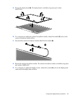
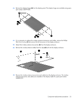
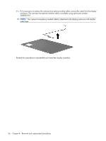
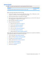
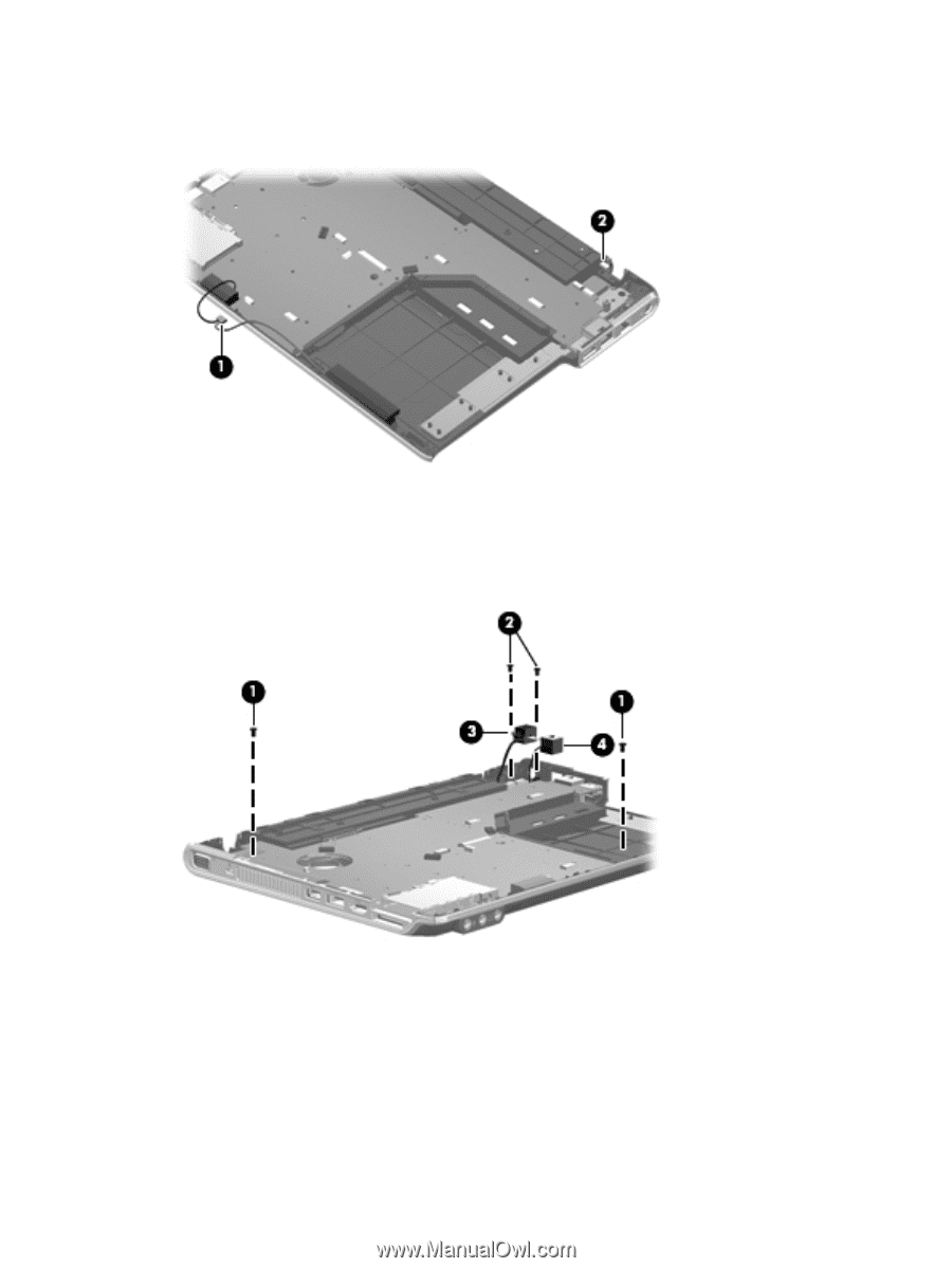
Remove the system board: 1. Disconnect the speaker cable (1) and the Bluetooth module cable (2) from the system board. 2. Remove the two Phillips PM2.5×5.0 screws (1) that secure the system board to the base enclosure. 3. Remove the two Phillips PM2.0×4.0 screws (2) that secure the power connector to the base enclosure. 4. Remove the power connector (3) and the RJ11 jack (4) from the clips in the base enclosure. 5. Flex the right side of the base enclosure (1) above the USB port and RJ45 jack. 58 Chapter 4 Removal and replacement procedures
-
 1
1 -
2
-
3
-
4
-
5
-
6
-
7
-
8
-
9
-
10
-
11
-
12
-
13
-
14
-
15
-
16
-
17
-
18
-
19
-
20
-
21
-
22
-
23
-
24
-
25
-
26
-
27
-
28
-
29
-
30
-
31
-
32
-
33
-
34
-
35
-
36
-
37
-
38
-
39
-
40
-
41
-
42
-
43
-
44
-
45
-
46
-
47
-
48
-
49
-
50
-
51
-
52
-
53
-
54
-
55
-
56
-
57
-
58
-
59
-
60
-
 61
61 -
 62
62 -
 63
63 -
 64
64 -
 65
65 -
 66
66 -
 67
67 -
 68
68 -
 69
69 -
 70
70 -
 71
71 -
72
-
73
-
74
-
75
-
76
-
77
-
78
-
79
-
80
-
81
-
82
-
83
-
84
-
85
-
86
-
87
-
88
-
89
-
90
-
91
-
92
-
93
-
94
-
95
-
96
-
97
-
98
-
99
-
100
-
101
-
102
-
103
-
104
-
105
-
106
-
107
-
108
-
109
-
110
-
111
-
112
-
113
-
114
-
115
-
116
-
117
-
118
-
119
-
120
-
121
-
122
-
123
-
124
-
125
-
126
-
127
-
128
-
129
-
130
 |
 |
Remove the system board:
1
.
Disconnect the speaker cable
(1)
and the Bluetooth module cable
(2)
from the system board.
2
.
Remove the two Phillips PM2.5×5.0 screws
(1)
that secure the system board to the base enclosure.
3
.
Remove the two Phillips PM2.0×4.0 screws
(2)
that secure the power connector to the base
enclosure.
4
.
Remove the power connector
(3)
and the RJ11 jack
(4)
from the clips in the base enclosure.
5
.
Flex the right side of the base enclosure
(1)
above the USB port and RJ45 jack.
58
Chapter
4
Removal and replacement procedures