HP Pavilion dv3000 HP Pavilion dv3000 Entertainment PC - Maintenance and Servi - Page 74
Modem module, Remove the modem module
 |
View all HP Pavilion dv3000 manuals
Add to My Manuals
Save this manual to your list of manuals |
Page 74 highlights
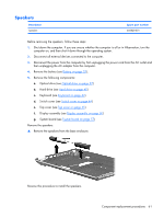
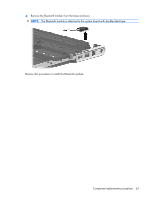
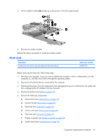
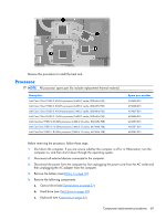
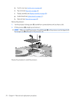
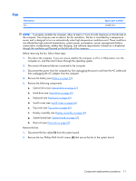
Modem module NOTE: The modem module spare part kits do not include a modem module cable. The modem module cable is included in the Cable Kit, spare part number 468827-001. Description For use in all countries and regions except Australia and New Zealand For use only in Australia and New Zealand Spare part number 468825-001 468825-011 Before removing the modem module, follow these steps: 1. Shut down the computer. If you are unsure whether the computer is off or in Hibernation, turn the computer on, and then shut it down through the operating system. 2. Disconnect all external devices connected to the computer. 3. Disconnect the power from the computer by first unplugging the power cord from the AC outlet and then unplugging the AC adapter from the computer. 4. Remove the battery (see Battery on page 32). 5. Remove the following components: a. Optical drive (see Optical drive on page 37) b. Hard drive (see Hard drive on page 40) c. Keyboard (see Keyboard on page 42) d. Switch cover (see Switch cover on page 44) e. Top cover (see Top cover on page 45) f. Display assembly (see Display assembly on page 50) g. System board (see System board on page 57) Remove the modem module: 1. Turn the system board upside down, with the battery connector toward you. 2. Remove the modem module cable (1) from the clips (2) built into the system board. NOTE: The modem module cable is included in the Cable Kit, spare part number 468827-001 3. Remove the two Phillips PM2.5×4.0 screws (3) that secure the modem module to the system board. 66 Chapter 4 Removal and replacement procedures
-
 1
1 -
2
-
3
-
4
-
5
-
6
-
7
-
8
-
9
-
10
-
11
-
12
-
13
-
14
-
15
-
16
-
17
-
18
-
19
-
20
-
21
-
22
-
23
-
24
-
25
-
26
-
27
-
28
-
29
-
30
-
31
-
32
-
33
-
34
-
35
-
36
-
37
-
38
-
39
-
40
-
41
-
42
-
43
-
44
-
45
-
46
-
47
-
48
-
49
-
50
-
51
-
52
-
53
-
54
-
55
-
56
-
57
-
58
-
59
-
60
-
61
-
62
-
63
-
64
-
65
-
66
-
67
-
68
-
 69
69 -
 70
70 -
 71
71 -
 72
72 -
 73
73 -
 74
74 -
 75
75 -
 76
76 -
 77
77 -
 78
78 -
 79
79 -
80
-
81
-
82
-
83
-
84
-
85
-
86
-
87
-
88
-
89
-
90
-
91
-
92
-
93
-
94
-
95
-
96
-
97
-
98
-
99
-
100
-
101
-
102
-
103
-
104
-
105
-
106
-
107
-
108
-
109
-
110
-
111
-
112
-
113
-
114
-
115
-
116
-
117
-
118
-
119
-
120
-
121
-
122
-
123
-
124
-
125
-
126
-
127
-
128
-
129
-
130
 |
 |