HP Pavilion dv3000 HP Pavilion dv3000 Entertainment PC - Maintenance and Servi - Page 60
and the top and bottom edges, Flex the inside edges of the left and right sides
 |
View all HP Pavilion dv3000 manuals
Add to My Manuals
Save this manual to your list of manuals |
Page 60 highlights
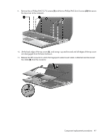
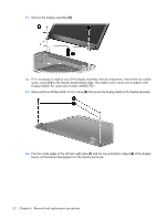
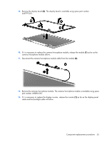
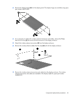
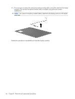
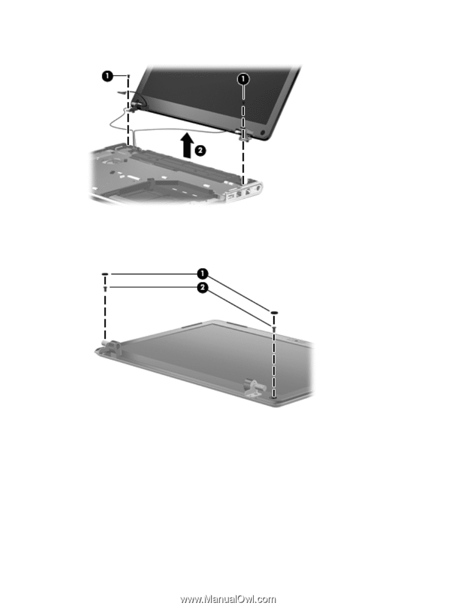
11. Remove the display assembly (2). 12. If it is necessary to replace any of the display assembly internal components, remove the two rubber screw covers (1) on the display bezel bottom edge. The rubber screw covers are included in the Display Rubber Kit, spare part number 468802-001. 13. Remove the two Phillips PM2.5×5.0 screws (2) that secure the display bezel to the display assembly. 14. Flex the inside edges of the left and right sides (1) and the top and bottom edges (2) of the display bezel until the bezel disengages from the display enclosure. 52 Chapter 4 Removal and replacement procedures
-
 1
1 -
2
-
3
-
4
-
5
-
6
-
7
-
8
-
9
-
10
-
11
-
12
-
13
-
14
-
15
-
16
-
17
-
18
-
19
-
20
-
21
-
22
-
23
-
24
-
25
-
26
-
27
-
28
-
29
-
30
-
31
-
32
-
33
-
34
-
35
-
36
-
37
-
38
-
39
-
40
-
41
-
42
-
43
-
44
-
45
-
46
-
47
-
48
-
49
-
50
-
51
-
52
-
53
-
54
-
 55
55 -
 56
56 -
 57
57 -
 58
58 -
 59
59 -
 60
60 -
 61
61 -
 62
62 -
 63
63 -
 64
64 -
 65
65 -
66
-
67
-
68
-
69
-
70
-
71
-
72
-
73
-
74
-
75
-
76
-
77
-
78
-
79
-
80
-
81
-
82
-
83
-
84
-
85
-
86
-
87
-
88
-
89
-
90
-
91
-
92
-
93
-
94
-
95
-
96
-
97
-
98
-
99
-
100
-
101
-
102
-
103
-
104
-
105
-
106
-
107
-
108
-
109
-
110
-
111
-
112
-
113
-
114
-
115
-
116
-
117
-
118
-
119
-
120
-
121
-
122
-
123
-
124
-
125
-
126
-
127
-
128
-
129
-
130
 |
 |
11
.
Remove the display assembly
(2)
.
12
.
If it is necessary to replace any of the display assembly internal components, remove the two rubber
screw covers
(1)
on the display bezel bottom edge. The rubber screw covers are included in the
Display Rubber Kit, spare part number 468802-001.
13
.
Remove the two Phillips PM2.5×5.0 screws
(2)
that secure the display bezel to the display assembly.
14
.
Flex the inside edges of the left and right sides
(1)
and the top and bottom edges
(2)
of the display
bezel until the bezel disengages from the display enclosure.
52
Chapter
4
Removal and replacement procedures