HP Pavilion dv3000 HP Pavilion dv3000 Entertainment PC - Maintenance and Servi - Page 67
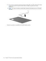
Lift the back edge of the system board, above the eSATA connector and HDMI connector.
 |
View all HP Pavilion dv3000 manuals
Add to My Manuals
Save this manual to your list of manuals |
Page 67 highlights
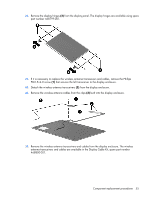
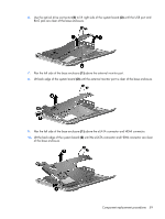
6. Use the optical drive connector (2) to lift right side of the system board (3) until the USB port and RJ45 jack are clear of the base enclosure. 7. Flex the left side of the base enclosure (1) above the external monitor port. 8. Lift back edge of the system board (2) until the external monitor port is clear of the base enclosure. 9. Flex the left side of the base enclosure (1) above the eSATA connector and HDMI connector. 10. Lift the back edge of the system board (2) until the eSATA connector and HDMI connector are clear of the base enclosure. Component replacement procedures 59
-
 1
1 -
2
-
3
-
4
-
5
-
6
-
7
-
8
-
9
-
10
-
11
-
12
-
13
-
14
-
15
-
16
-
17
-
18
-
19
-
20
-
21
-
22
-
23
-
24
-
25
-
26
-
27
-
28
-
29
-
30
-
31
-
32
-
33
-
34
-
35
-
36
-
37
-
38
-
39
-
40
-
41
-
42
-
43
-
44
-
45
-
46
-
47
-
48
-
49
-
50
-
51
-
52
-
53
-
54
-
55
-
56
-
57
-
58
-
59
-
60
-
61
-
 62
62 -
 63
63 -
 64
64 -
 65
65 -
 66
66 -
 67
67 -
 68
68 -
 69
69 -
 70
70 -
 71
71 -
 72
72 -
73
-
74
-
75
-
76
-
77
-
78
-
79
-
80
-
81
-
82
-
83
-
84
-
85
-
86
-
87
-
88
-
89
-
90
-
91
-
92
-
93
-
94
-
95
-
96
-
97
-
98
-
99
-
100
-
101
-
102
-
103
-
104
-
105
-
106
-
107
-
108
-
109
-
110
-
111
-
112
-
113
-
114
-
115
-
116
-
117
-
118
-
119
-
120
-
121
-
122
-
123
-
124
-
125
-
126
-
127
-
128
-
129
-
130
 |
 |

6
.
Use the optical drive connector
(2)
to lift right side of the system board
(3)
until the USB port and
RJ45 jack are clear of the base enclosure.
7
.
Flex the left side of the base enclosure
(1)
above the external monitor port.
8
.
Lift back edge of the system board
(2)
until the external monitor port is clear of the base enclosure.
9
.
Flex the left side of the base enclosure
(1)
above the eSATA connector and HDMI connector.
10
.
Lift the back edge of the system board
(2)
until the eSATA connector and HDMI connector are clear
of the base enclosure.
Component replacement procedures
59