HP Pavilion dv3000 HP Pavilion dv3000 Entertainment PC - Maintenance and Servi - Page 65
System board, When replacing the system board - rtc battery
 |
View all HP Pavilion dv3000 manuals
Add to My Manuals
Save this manual to your list of manuals |
Page 65 highlights
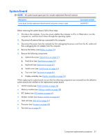
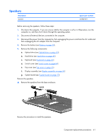
System board NOTE: All system board spare part kits include replacement thermal material. Description System board (includes replacement thermal material and power connector cable) Spare part number 468499-001 Before removing the system board, follow these steps: 1. Shut down the computer. If you are unsure whether the computer is off or in Hibernation, turn the computer on, and then shut it down through the operating system. 2. Disconnect all external devices connected to the computer. 3. Disconnect the power from the computer by first unplugging the power cord from the AC outlet and then unplugging the AC adapter from the computer. 4. Remove the battery (see Battery on page 32). 5. Remove the following components: a. Optical drive (see Optical drive on page 37) b. Hard drive (see Hard drive on page 40) c. Keyboard (see Keyboard on page 42) d. Switch cover (see Switch cover on page 44) e. Top cover (see Top cover on page 45) f. Display assembly (see Display assembly on page 50) When replacing the system board, be sure that the following components are removed from the defective system board and installed on the replacement system board: ● WLAN module (see WLAN module on page 34) ● Memory modules (see Memory module on page 38) ● RTC battery (see RTC battery on page 64) ● Modem module (see Modem module on page 66) ● Heat sink (see Heat sink on page 67) ● Processor (see Processor on page 69) ● Fan (see Fan on page 71) Component replacement procedures 57
-
 1
1 -
2
-
3
-
4
-
5
-
6
-
7
-
8
-
9
-
10
-
11
-
12
-
13
-
14
-
15
-
16
-
17
-
18
-
19
-
20
-
21
-
22
-
23
-
24
-
25
-
26
-
27
-
28
-
29
-
30
-
31
-
32
-
33
-
34
-
35
-
36
-
37
-
38
-
39
-
40
-
41
-
42
-
43
-
44
-
45
-
46
-
47
-
48
-
49
-
50
-
51
-
52
-
53
-
54
-
55
-
56
-
57
-
58
-
59
-
 60
60 -
 61
61 -
 62
62 -
 63
63 -
 64
64 -
 65
65 -
 66
66 -
 67
67 -
 68
68 -
 69
69 -
 70
70 -
71
-
72
-
73
-
74
-
75
-
76
-
77
-
78
-
79
-
80
-
81
-
82
-
83
-
84
-
85
-
86
-
87
-
88
-
89
-
90
-
91
-
92
-
93
-
94
-
95
-
96
-
97
-
98
-
99
-
100
-
101
-
102
-
103
-
104
-
105
-
106
-
107
-
108
-
109
-
110
-
111
-
112
-
113
-
114
-
115
-
116
-
117
-
118
-
119
-
120
-
121
-
122
-
123
-
124
-
125
-
126
-
127
-
128
-
129
-
130
 |
 |