HP t505 Troubleshooting Guide t505 Flexible Thin Client - Page 10
Rear Panel Components, Installing the Rubber Feet, CAUTION
 |
View all HP t505 manuals
Add to My Manuals
Save this manual to your list of manuals |
Page 10 highlights
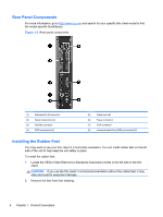
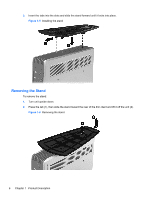
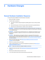
Rear Panel Components For more information, go to http://www.hp.com and search for your specific thin client model to find the model-specific QuickSpecs. Figure 1-3 Rear panel components (1) Ethernet RJ-45 connector (2) Serial connectors (4) (3) Parallel connector (4) PS/2 connectors (2) (5) Cable lock slot (6) Power connector (7) VGA connector (8) Universal serial bus (USB) connectors (2) Installing the Rubber Feet You may want to use your thin client in a horizontal orientation. You can install rubber feet on the left side of the unit to help keep the unit safely in place. To install the rubber feet: 1. Locate the VESA (Video Electronics Standards Association) holes in the left side of the thin client. CAUTION: If you use the thin client in a horizontal orientation without the rubber feet, it may slide and result in equipment damage. 2. Remove the feet from their backing. 4 Chapter 1 Product Description
-
 1
1 -
2
-
3
-
4
-
 5
5 -
 6
6 -
 7
7 -
 8
8 -
 9
9 -
 10
10 -
 11
11 -
 12
12 -
 13
13 -
 14
14 -
 15
15 -
16
-
17
-
18
-
19
-
20
-
21
-
22
-
23
-
24
-
25
-
26
-
27
-
28
-
29
-
30
-
31
-
32
-
33
-
34
-
35
-
36
-
37
-
38
-
39
-
40
-
41
-
42
-
43
-
44
-
45
-
46
-
47
-
48
-
49
-
50
-
51
-
52
-
53
-
54
-
55
-
56
-
57
-
58
-
59
-
60
-
61
-
62
-
63
-
64
-
65
-
66
-
67
-
68
-
69
-
70
-
71
 |
 |
