HP t505 Troubleshooting Guide t505 Flexible Thin Client - Page 20
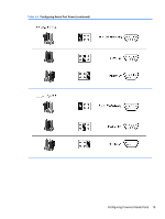
Table, Configuring Serial Port Power,
 |
View all HP t505 manuals
Add to My Manuals
Save this manual to your list of manuals |
Page 20 highlights
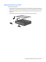
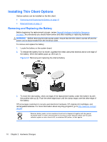
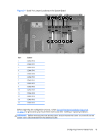
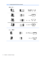
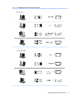
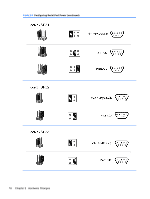
To configure the serial ports: 1. Locate the serial port and jumper. 2. Place jumpers on the appropriate pins. (See Table 2-3 Configuring Serial Port Power on page 15 to determine the appropriate pins.) CAUTION: An unsupported configuration can cause severe equipment damage. Carefully verify COM Port Jumper locations and supported configurations before you configure a serial port. See Figure 2-4 Serial Port Jumper Locations on the System Board on page 13 and Table 2-3 Configuring Serial Port Power on page 15 for Jumper locations and supported configurations. Table 2-1 COM Port Default Configuration pin # COM1 COM2 pin 1 DCD +5V pin 2 RXD RXD pin 3 TXD TXD pin 4 DTR DTR pin 5 GND GND pin 6 DSR DSR pin 7 RTS RTS pin 8 CTS RXD (TTL) pin 9 RI TXD (TTL) COM3 +5V RXD TXD DTR GND DSR RTS CTS RI COM4 +5V RXD TXD DTR GND DSR RTS CTS RI Table 2-2 COM Port Functionality pin # COM1 (Standard) pin 1 pin 2 DCD RXD pin 3 TXD pin 4 pin 5 pin 6 pin 7 pin 8 DTR GND DSR RTS CTS pin 9 RI COM2-Cable Connection (Customized) COM3 (Customized) +5V/DCD +5V/+12V/DCD RXD/TXD/RXD (TTL)/ RXD/TXD TXD (TTL) TXD/RXD/TXD (TTL)/ TXD/RXD RXD (TTL) DTR/+5V DTR/+5V/+12V GND GND DSR DSR RTS RTS RXD/TXD/RXD (TTL)/ CTS TXD (TTL) TXD/RXD/TXD (TTL)/ RI RXD (TTL) COM4 (Customized) +5V/+12V/DCD RXD/TXD TXD/RXD DTR/+5V/+12V GND DSR RTS CTS RI 14 Chapter 2 Hardware Changes
-
 1
1 -
2
-
3
-
4
-
5
-
6
-
7
-
8
-
9
-
10
-
11
-
12
-
13
-
14
-
 15
15 -
 16
16 -
 17
17 -
 18
18 -
 19
19 -
 20
20 -
 21
21 -
 22
22 -
 23
23 -
 24
24 -
 25
25 -
26
-
27
-
28
-
29
-
30
-
31
-
32
-
33
-
34
-
35
-
36
-
37
-
38
-
39
-
40
-
41
-
42
-
43
-
44
-
45
-
46
-
47
-
48
-
49
-
50
-
51
-
52
-
53
-
54
-
55
-
56
-
57
-
58
-
59
-
60
-
61
-
62
-
63
-
64
-
65
-
66
-
67
-
68
-
69
-
70
-
71
 |
 |
