Hitachi 55HDS52 Owners Guide - Page 13
Connecting External Video Sources - plasma hdtv
 |
View all Hitachi 55HDS52 manuals
Add to My Manuals
Save this manual to your list of manuals |
Page 13 highlights
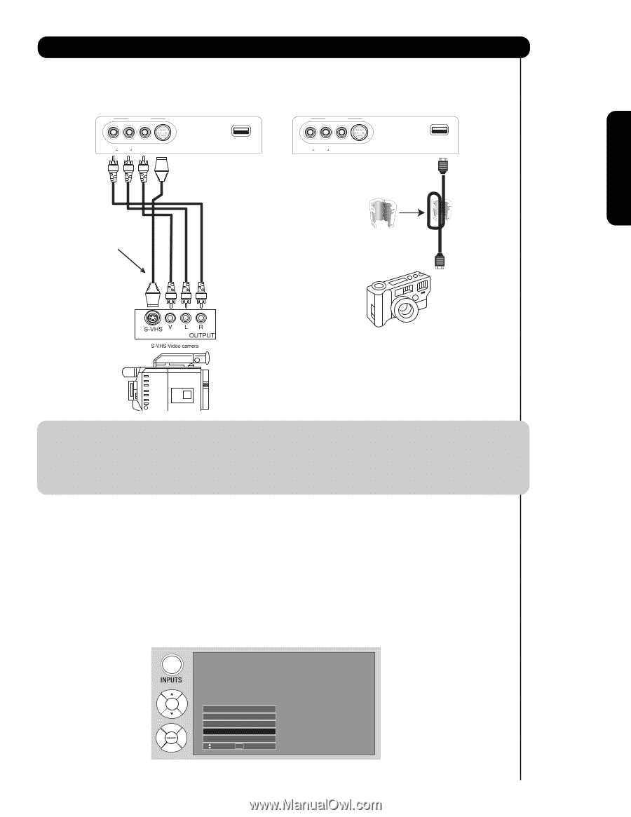
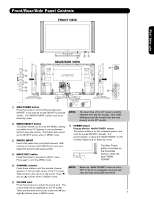
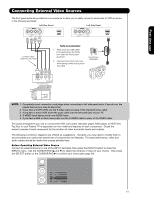
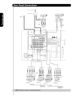
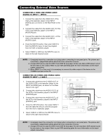
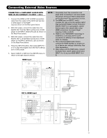
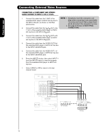
First time use Connecting External Video Sources The front panel jacks are provided as a convenience to allow you to easily connect a camcorder or VCR as shown in the following examples: Left Side Panel INPUT 5 Left Side Panel INPUT 5 R L/MONO ̆ AUDIO VIDEO S-VIDEO PHOTO INPUT R L/MONO ̆ AUDIO VIDEO S-VIDEO PHOTO INPUT S-Video Cable (Optional, see note) Ferrite Core Instructions: 1. Wrap once the USB cable (not supplied) on the ferrite core near the Photo Input as shown. 2. Fold and close the ferrite core while being careful not to pinch the cable. Ferrite Core (Supplied) NOTE: 1. Completely insert connection cord plugs when connecting to left side panel jacks. If you do not, the played back picture may be abnormal. 2. If you have a S-VHS VCR, use the S-Video cable in place of the standard video cable. 3. If you have a mono VCR, insert the audio cable into the left audio jack of your TV. 4. S-VIDEO input takes priority over VIDEO input. 5. If you have a VHS or 8mm camcorder, use the S-VIDEO cable in place of the VIDEO cable. The exact arrangement you use to connect the VCR, camcorder, laserdisc player, DVD player, or HDTV Set Top Box to your Plasma TV is dependent on the model and features of each component. Check the owner's manual of each component for the location of video and audio inputs and outputs. The following connection diagrams are offered as suggestions. However, you may need to modify them to accommodate your particular assortment of components and features. For best performance, video and audio cables should be made from coaxial shielded wire. Before Operating External Video Source Connect an external source to one of the INPUT terminals, then press the INPUTS button to show the INPUTS menu. Use the CURSOR PAD (̆ and ̄) to select the Antenna or Input of your choice. Then press the SELECT button or the CURSOR PAD ̈ to confirm your choice (see page 24). Input 5 Photo Input Cable Air Input 1 Move SEL Sel. 13
-
 1
1 -
2
-
3
-
4
-
5
-
6
-
7
-
 8
8 -
 9
9 -
 10
10 -
 11
11 -
 12
12 -
 13
13 -
 14
14 -
 15
15 -
 16
16 -
 17
17 -
 18
18 -
19
-
20
-
21
-
22
-
23
-
24
-
25
-
26
-
27
-
28
-
29
-
30
-
31
-
32
-
33
-
34
-
35
-
36
-
37
-
38
-
39
-
40
-
41
-
42
-
43
-
44
-
45
-
46
-
47
-
48
-
49
-
50
-
51
-
52
-
53
-
54
-
55
-
56
-
57
-
58
-
59
-
60
-
61
-
62
-
63
-
64
-
65
-
66
-
67
-
68
-
69
-
70
-
71
-
72
-
73
-
74
-
75
-
76
-
77
-
78
-
79
-
80
-
81
-
82
-
83
-
84
-
85
-
86
-
87
-
88
 |
 |