Husqvarna AUTOMOWER 520 Owner Manual - Page 6
Automower® 520, Automower® 550
 |
View all Husqvarna AUTOMOWER 520 manuals
Add to My Manuals
Save this manual to your list of manuals |
Page 6 highlights
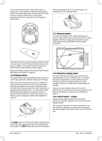
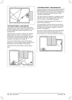
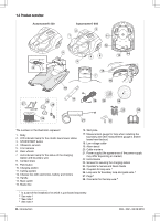
1.3 Product overview Automower® 520 Automower® 550 3 2 1 11 12 9 4 6 5 14 13 8 15 7 16 10 25 27 28 26 17 18 19 20 23 24 21 22 The numbers in the illustration represent: 1. Body 2. LED indicator lamp for the robotic lawnmower status 3. STOP/START button 4. Ultrasonic sensors 5. Front wheels 6. Rear wheels 7. LED indicator lamp for the status of the charging station and boundary wire 8. Contact strips 9. Park button 10. Charging station 11. Cutting system 12. Chassis box with electronics, battery and motors 13. Handle 14. Main switch 15. Blade disc 16. Skid plate 17. Measurement gauge for help when installing the boundary wire (the measurement gauge is broken loose from the box) 18. Low voltage cable 19. Alarm decal 20. Cable markers 21. Power supply (the appearance of the power supply may differ depending on market) 22. Extra blades 23. Screws for securing the charging station 24. Operator's manual and Quick Guide 25. Couplers for loop wire 1 26. Loop wire for boundary loop and guide wire 2 27. Pegs 3 28. Connector for the loop wire 4 1 Is a part of the Installation kit which is purchased separately. 2 See note 1 3 See note 1 4 See note 1 6 - Introduction 362 - 002 - 06.02.2018
-
 1
1 -
 2
2 -
 3
3 -
 4
4 -
 5
5 -
 6
6 -
 7
7 -
 8
8 -
 9
9 -
 10
10 -
 11
11 -
 12
12 -
13
-
14
-
15
-
16
-
17
-
18
-
19
-
20
-
21
-
22
-
23
-
24
-
25
-
26
-
27
-
28
-
29
-
30
-
31
-
32
-
33
-
34
-
35
-
36
-
37
-
38
-
39
-
40
-
41
-
42
-
43
-
44
-
45
-
46
-
47
-
48
-
49
-
50
-
51
-
52
-
53
-
54
-
55
-
56
-
57
-
58
-
59
-
60
-
61
-
62
-
63
-
64
 |
 |
