Intel BLKDH61WWB3 Product Specification - Page 14
Table 2., Components Shown - lga1155
 |
View all Intel BLKDH61WWB3 manuals
Add to My Manuals
Save this manual to your list of manuals |
Page 14 highlights
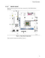
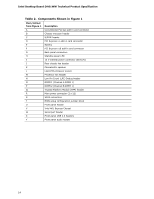
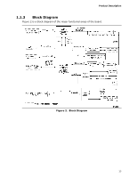
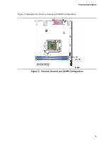
Intel Desktop Board DH61WW Technical Product Specification Table 2. Components Shown in Figure 1 Item/callout from Figure 1 Description A Conventional PCI bus add-in card connector B Chassis intrusion header C S/PDIF header D PCI Express x1 add-in card connector E Battery F PCI Express x16 add-in card connector G Back panel connectors H Standby power LED I 12 V internal power connector (ATX12V) J Rear chassis fan header K Piezoelectric speaker L LGA1155 processor socket M Processor fan header N Low Pin Count (LPC) Debug header O DIMM 1 (Channel A DIMM 1) P DIMM 2 (Channel B DIMM 1) Q Trusted Platform Module (TPM) header R Main power connector (2 x 12) S SATA connectors T BIOS setup configuration jumper block U Front panel header V Intel H61 Express Chipset W Serial port header X Front panel USB 2.0 headers Y Front panel audio header 14
-
 1
1 -
2
-
3
-
4
-
5
-
6
-
7
-
8
-
 9
9 -
 10
10 -
 11
11 -
 12
12 -
 13
13 -
 14
14 -
 15
15 -
 16
16 -
 17
17 -
 18
18 -
 19
19 -
20
-
21
-
22
-
23
-
24
-
25
-
26
-
27
-
28
-
29
-
30
-
31
-
32
-
33
-
34
-
35
-
36
-
37
-
38
-
39
-
40
-
41
-
42
-
43
-
44
-
45
-
46
-
47
-
48
-
49
-
50
-
51
-
52
-
53
-
54
-
55
-
56
-
57
-
58
-
59
-
60
-
61
-
62
-
63
-
64
-
65
-
66
-
67
-
68
-
69
-
70
-
71
-
72
-
73
-
74
-
75
-
76
-
77
-
78
-
79
-
80
-
81
-
82
-
83
-
84
-
85
-
86
 |
 |