Intel BLKDH61WWB3 Product Specification - Page 46
Add-in Card Connectors
 |
View all Intel BLKDH61WWB3 manuals
Add to My Manuals
Save this manual to your list of manuals |
Page 46 highlights
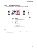
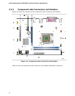
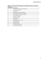
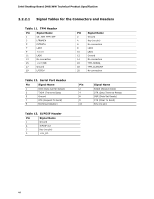
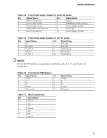
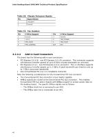
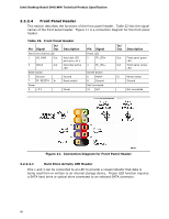
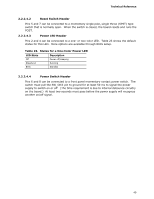
Intel Desktop Board DH61WW Technical Product Specification Table 18. Chassis Intrusion Header Pin Signal Name 1 Intruder# 2 Ground Table 19. Fan Headers Pin 4-Wire Support 1 Ground 2 +12 V 3 FAN_TACH 4 FAN_CONTROL Pin 3-Wire Support 3 Ground 2 FAN_POWER 1 FAN_TACH N/A N/A 2.2.2.2 Add-in Card Connectors The board has the following add-in card connectors: • PCI Express 2.0 x16: one PCI Express 2.0 x16 connector. This connector supports simultaneous transfer speeds of up to 8 GB/s of peak bandwidth per direction. • PCI Express 2.0 x1: one PCI Express 2.0 x1 connector. The x1 interface supports simultaneous transfer speeds up to 1 GB/s of peak bandwidth per direction and up to 2 GB/s concurrent bandwidth. • One Conventional PCI (rev 2.3 compliant) connector. Note the following considerations for the Conventional PCI bus connector: • The Conventional PCI bus connector is bus master capable. • SMBus signals are routed to the Conventional PCI bus connector. This enables Conventional PCI bus add-in boards with SMBus support to access sensor data on the desktop board. The specific SMBus signals are as follows: ⎯ The SMBus clock line is connected to pin A40. ⎯ The SMBus data line is connected to pin A41. 46
-
 1
1 -
2
-
3
-
4
-
5
-
6
-
7
-
8
-
9
-
10
-
11
-
12
-
13
-
14
-
15
-
16
-
17
-
18
-
19
-
20
-
21
-
22
-
23
-
24
-
25
-
26
-
27
-
28
-
29
-
30
-
31
-
32
-
33
-
34
-
35
-
36
-
37
-
38
-
39
-
40
-
 41
41 -
 42
42 -
 43
43 -
 44
44 -
 45
45 -
 46
46 -
 47
47 -
 48
48 -
 49
49 -
 50
50 -
 51
51 -
52
-
53
-
54
-
55
-
56
-
57
-
58
-
59
-
60
-
61
-
62
-
63
-
64
-
65
-
66
-
67
-
68
-
69
-
70
-
71
-
72
-
73
-
74
-
75
-
76
-
77
-
78
-
79
-
80
-
81
-
82
-
83
-
84
-
85
-
86
 |
 |