Intel BLKDH61WWB3 Product Specification - Page 40
Connectors and Headers
 |
View all Intel BLKDH61WWB3 manuals
Add to My Manuals
Save this manual to your list of manuals |
Page 40 highlights
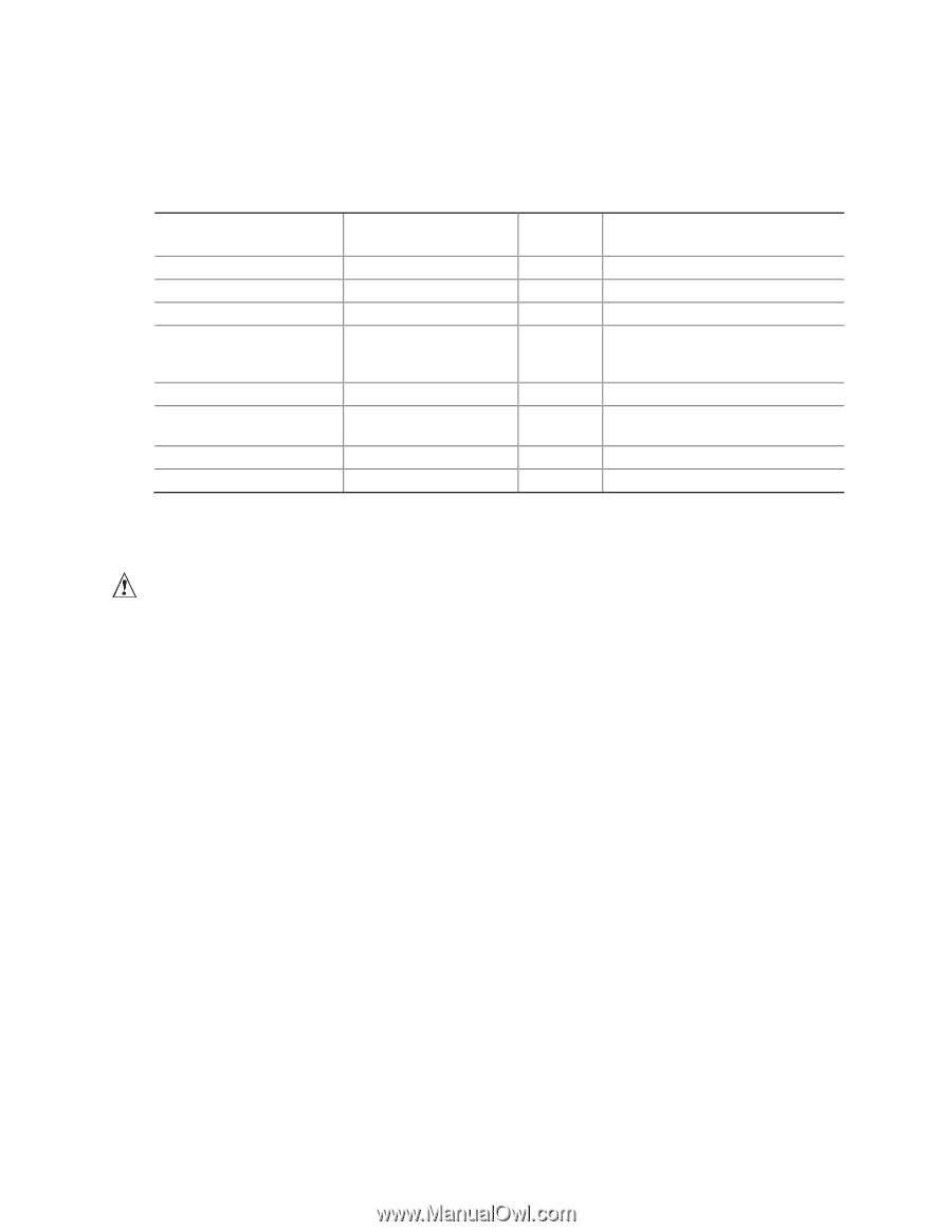
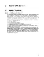
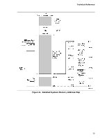
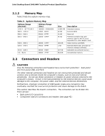
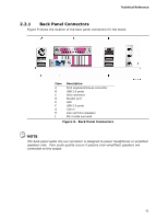
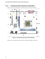
Intel Desktop Board DH61WW Technical Product Specification 2.1.2 Memory Map Table 9 lists the system memory map. Table 9. System Memory Map Address Range (decimal) Address Range (hex) 1024 K - 16777216K K 960 K - 1024 K 100000 - 400000000 F0000 - FFFFF 896 K - 960 K E0000 - EFFFF 800 K - 896 K C8000 - DFFFF 640 K - 800 K 639 K - 640 K 512 K - 639 K 0 K - 512 K A0000 - C7FFF 9FC00 - 9FFFF 80000 - 9FBFF 00000 - 7FFFF Size 16382 MB 64 KB 64 KB 96 KB 160 KB 1 KB 127 KB 512 KB Description Extended memory Runtime BIOS Reserved Potential available high DOS memory (open to the PCI bus). Dependent on video adapter used. Video memory and BIOS Extended BIOS data (movable by memory manager software) Extended conventional memory Conventional memory 2.2 Connectors and Headers CAUTION Only the following connectors and headers have overcurrent protection: back panel and front panel USB, and PS/2. The other internal connectors and headers are not overcurrent protected and should connect only to devices inside the computer's chassis, such as fans and internal peripherals. Do not use these connectors or headers to power devices external to the computer's chassis. A fault in the load presented by the external devices could cause damage to the computer, the power cable, and the external devices themselves. Furthermore, improper connection of USB header single wire connectors may eventually overload the overcurrent protection and cause damage to the board. This section describes the board's connectors. The connectors can be divided into these groups: • Back panel I/O connectors • Component-side I/O connectors and headers (see page 42) 40
-
 1
1 -
2
-
3
-
4
-
5
-
6
-
7
-
8
-
9
-
10
-
11
-
12
-
13
-
14
-
15
-
16
-
17
-
18
-
19
-
20
-
21
-
22
-
23
-
24
-
25
-
26
-
27
-
28
-
29
-
30
-
31
-
32
-
33
-
34
-
 35
35 -
 36
36 -
 37
37 -
 38
38 -
 39
39 -
 40
40 -
 41
41 -
 42
42 -
 43
43 -
 44
44 -
 45
45 -
46
-
47
-
48
-
49
-
50
-
51
-
52
-
53
-
54
-
55
-
56
-
57
-
58
-
59
-
60
-
61
-
62
-
63
-
64
-
65
-
66
-
67
-
68
-
69
-
70
-
71
-
72
-
73
-
74
-
75
-
76
-
77
-
78
-
79
-
80
-
81
-
82
-
83
-
84
-
85
-
86
 |
 |