Intel BLKDH61WWB3 Product Specification - Page 35
Fan Headers, 16.2.3, LAN Wake Capabilities, CAUTION
 |
View all Intel BLKDH61WWB3 manuals
Add to My Manuals
Save this manual to your list of manuals |
Page 35 highlights
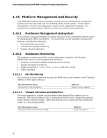
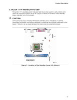
Product Description 1.16.2.2 Fan Headers The function/operation of the fan headers is as follows: • The fans are on when the board is in the S0 state • The fans are off when the board is in the S3, S4, or S5 state • Each fan header is wired to a fan tachometer input of the hardware monitoring and fan control ASIC • All fan headers support closed-loop fan control that can adjust the fan speed or switch the fan on or off as needed • All fan headers have a +12 V DC connection • 4-pin fan headers are controlled by Pulse Width Modulation • The rear fan header also supports linear fan control on 3-wire fans For information about The location of the fan headers The location of the fan headers and sensors for thermal monitoring Refer to Figure 10, page 42 Figure 6, page 29 1.16.2.3 LAN Wake Capabilities CAUTION For LAN wake capabilities, the +5 V standby line for the power supply must be capable of providing adequate +5 V standby current. Failure to provide adequate standby current when implementing LAN wake capabilities can damage the power supply. LAN wake capabilities enable remote wake-up of the computer through a network. The LAN subsystem monitors network traffic at the Media Independent Interface. Upon detecting a Magic Packet* frame, the LAN subsystem asserts a wake-up signal that powers up the computer. 35
-
 1
1 -
2
-
3
-
4
-
5
-
6
-
7
-
8
-
9
-
10
-
11
-
12
-
13
-
14
-
15
-
16
-
17
-
18
-
19
-
20
-
21
-
22
-
23
-
24
-
25
-
26
-
27
-
28
-
29
-
 30
30 -
 31
31 -
 32
32 -
 33
33 -
 34
34 -
 35
35 -
 36
36 -
 37
37 -
 38
38 -
 39
39 -
 40
40 -
41
-
42
-
43
-
44
-
45
-
46
-
47
-
48
-
49
-
50
-
51
-
52
-
53
-
54
-
55
-
56
-
57
-
58
-
59
-
60
-
61
-
62
-
63
-
64
-
65
-
66
-
67
-
68
-
69
-
70
-
71
-
72
-
73
-
74
-
75
-
76
-
77
-
78
-
79
-
80
-
81
-
82
-
83
-
84
-
85
-
86
 |
 |