Intel BLKDH61WWB3 Product Specification - Page 50
Front Panel USB Headers, 2.2.6, Low Pin Count LPC Debug Header
 |
View all Intel BLKDH61WWB3 manuals
Add to My Manuals
Save this manual to your list of manuals |
Page 50 highlights
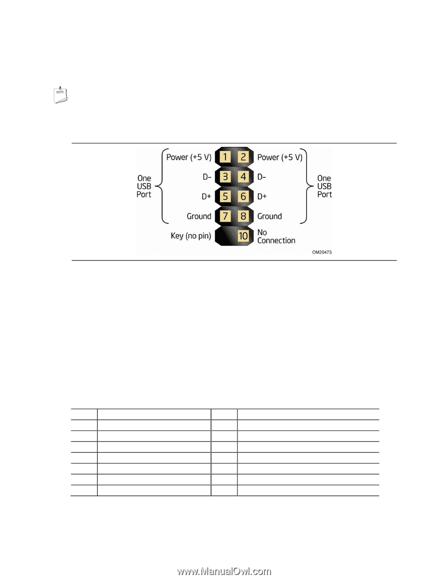
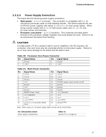
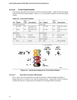
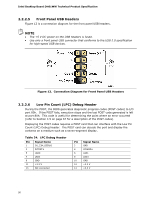
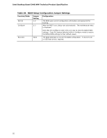
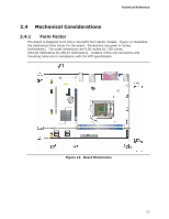
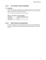
Intel Desktop Board DH61WW Technical Product Specification 2.2.2.5 Front Panel USB Headers Figure 12 is a connection diagram for the front panel USB headers. NOTE • The +5 V DC power on the USB headers is fused. • Use only a front panel USB connector that conforms to the USB 2.0 specification for high-speed USB devices. Figure 12. Connection Diagram for Front Panel USB Headers 2.2.2.6 Low Pin Count (LPC) Debug Header During the POST, the BIOS generates diagnostic progress codes (POST codes) to I/O port 80h. If the POST fails, execution stops and the last POST code generated is left at port 80h. This code is useful for determining the point where an error occurred (refer to Section 4.5 on page 67 for a description of the POST codes). Displaying the POST codes requires a POST card that can interface with the Low Pin Count (LPC) Debug header. The POST card can decode the port and display the contents on a medium such as a seven-segment display. Table 24. LPC Debug Header Pin Signal Name 1 CK_33M_DEBUG 3 PLTRST# 5 LAD0 7 LAD2 9 GND 11 +3.3 V 13 Not connected Pin Signal Name 2 GND 4 LFRAME# 6 LAD1 8 LAD3 10 GND 12 +3.3 V 14 +3.3 V 50
-
 1
1 -
2
-
3
-
4
-
5
-
6
-
7
-
8
-
9
-
10
-
11
-
12
-
13
-
14
-
15
-
16
-
17
-
18
-
19
-
20
-
21
-
22
-
23
-
24
-
25
-
26
-
27
-
28
-
29
-
30
-
31
-
32
-
33
-
34
-
35
-
36
-
37
-
38
-
39
-
40
-
41
-
42
-
43
-
44
-
 45
45 -
 46
46 -
 47
47 -
 48
48 -
 49
49 -
 50
50 -
 51
51 -
 52
52 -
 53
53 -
 54
54 -
 55
55 -
56
-
57
-
58
-
59
-
60
-
61
-
62
-
63
-
64
-
65
-
66
-
67
-
68
-
69
-
70
-
71
-
72
-
73
-
74
-
75
-
76
-
77
-
78
-
79
-
80
-
81
-
82
-
83
-
84
-
85
-
86
 |
 |