Intel BLKDH61WWB3 Product Specification - Page 47
Power Supply Connectors, CAUTION
 |
View all Intel BLKDH61WWB3 manuals
Add to My Manuals
Save this manual to your list of manuals |
Page 47 highlights
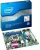
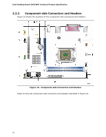
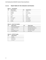
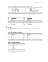
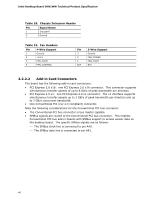
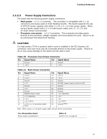
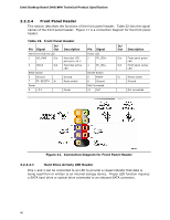
Technical Reference 2.2.2.3 Power Supply Connectors The board has the following power supply connectors: • Main power - a 2 x 12 connector. This connector is compatible with 2 x 10 connectors previously used on Intel Desktop boards. The board supports the use of ATX12V power supplies with either 2 x 10 or 2 x 12 main power cables. When using a power supply with a 2 x 10 main power cable, pins 11, 12, 23, and 24 must remain unconnected. • Processor core power - a 2 x 2 connector. This connector provides power directly to the processor voltage regulator and must always be used. Failure to do so will prevent the board from booting. CAUTION If a high power (75 W or greater) add-in card is installed in the PCI Express x16 connector, that card must also be connected directly to the power supply. Failure to do so may cause damage to the board and the add-in card. Table 20. Processor Core Power Connector Pin Signal Name Pin Signal Name 1 Ground 2 Ground 3 +12 V 4 +12 V Table 21. Main Power Connector Pin Signal Name Pin 1 +3.3 V 13 2 +3.3 V 14 3 Ground 15 4 +5 V 16 5 Ground 17 6 +5 V 18 7 Ground 19 8 PWRGD (Power Good) 20 9 +5 V (Standby) 21 10 +12 V 22 11 +12 V (Note) 23 12 +3.3 V 2 x 12 connector detect 24 (Note) Signal Name +3.3 V −12 V Ground PS-ON# (power supply remote on/off) Ground Ground Ground −5 V (obsolete) +5 V +5 V +5 V (Note) Ground (Note) Note: When using a 2 x 10 power supply cable, this pin will be unconnected. For information about Power supply considerations Refer to Section 2.5.1 on page 54 47
-
 1
1 -
2
-
3
-
4
-
5
-
6
-
7
-
8
-
9
-
10
-
11
-
12
-
13
-
14
-
15
-
16
-
17
-
18
-
19
-
20
-
21
-
22
-
23
-
24
-
25
-
26
-
27
-
28
-
29
-
30
-
31
-
32
-
33
-
34
-
35
-
36
-
37
-
38
-
39
-
40
-
41
-
 42
42 -
 43
43 -
 44
44 -
 45
45 -
 46
46 -
 47
47 -
 48
48 -
 49
49 -
 50
50 -
 51
51 -
 52
52 -
53
-
54
-
55
-
56
-
57
-
58
-
59
-
60
-
61
-
62
-
63
-
64
-
65
-
66
-
67
-
68
-
69
-
70
-
71
-
72
-
73
-
74
-
75
-
76
-
77
-
78
-
79
-
80
-
81
-
82
-
83
-
84
-
85
-
86
 |
 |