Intel BLKDX58OG Product Specification - Page 9

Regulatory Compliance and Battery Disposal Information, s

Page 9 highlights

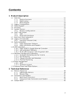
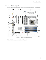
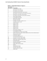
Contents 5 Regulatory Compliance and Battery Disposal Information 5.1 Regulatory Compliance 79 5.1.1 Safety Standards 79 5.1.2 European Union Declaration of Conformity Statement 80 5.1.3 Product Ecology Statements 81 5.1.4 EMC Regulations 83 5.1.5 ENERGY STAR* 5.0, e-Standby, and ErP Compliance 86 5.1.6 Regulatory Compliance Marks (Board Level 87 5.2 Battery Disposal Information 88 Figures 1. Major Board Components 13 2. Block Diagram 15 3. Memory Channel and DIMM Configuration 19 4. Back Panel Audio Connectors 24 5. LAN Connector LED Locations 26 6. Thermal Sensors and Fan Headers 28 7. Locations of Onboard LED Indicators 37 8. Location of the Power and Reset Buttons 38 9. Detailed System Memory Address Map 40 10. Back Panel Connectors 42 11. Component-side Connectors and Headers 43 12. Connection Diagram for Front Panel Header 50 13. Connection Diagram for Front Panel USB Headers 52 14. Location of the Jumper Block 53 15. Board Dimensions 55 16. Localized High Temperature Zones 58 ix

  • 1
  • 2
  • 3
  • 4
  • 5
  • 6
  • 7
  • 8
  • 9
  • 10
  • 11
  • 12
  • 13
  • 14
  • 15
  • 16
  • 17
  • 18
  • 19
  • 20
  • 21
  • 22
  • 23
  • 24
  • 25
  • 26
  • 27
  • 28
  • 29
  • 30
  • 31
  • 32
  • 33
  • 34
  • 35
  • 36
  • 37
  • 38
  • 39
  • 40
  • 41
  • 42
  • 43
  • 44
  • 45
  • 46
  • 47
  • 48
  • 49
  • 50
  • 51
  • 52
  • 53
  • 54
  • 55
  • 56
  • 57
  • 58
  • 59
  • 60
  • 61
  • 62
  • 63
  • 64
  • 65
  • 66
  • 67
  • 68
  • 69
  • 70
  • 71
  • 72
  • 73
  • 74
  • 75
  • 76
  • 77
  • 78
  • 79
  • 80
  • 81
  • 82
  • 83
  • 84
  • 85
  • 86
  • 87
  • 88
  • 89
  • 90
  • 91

Contents
ix
5
Regulatory Compliance and Battery Disposal Information
5.1
Regulatory Compliance
.....................................................................
79
5.1.1
Safety Standards
..................................................................
79
5.1.2
European Union Declaration of Conformity Statement
................
80
5.1.3
Product Ecology Statements
...................................................
81
5.1.4
EMC Regulations
..................................................................
83
5.1.5
ENERGY STAR* 5.0, e-Standby, and ErP Compliance
.................
86
5.1.6
Regulatory Compliance Marks (Board Level)
.............................
87
5.2
Battery Disposal Information
.............................................................
88
Figures
1.
Major Board Components
..................................................................
13
2.
Block Diagram
................................................................................
15
3.
Memory Channel and DIMM Configuration
...........................................
19
4.
Back Panel Audio Connectors
............................................................
24
5.
LAN Connector LED Locations
............................................................
26
6.
Thermal Sensors and Fan Headers
.....................................................
28
7.
Locations of Onboard LED Indicators
..................................................
37
8.
Location of the Power and Reset Buttons
............................................
38
9.
Detailed System Memory Address Map
...............................................
40
10. Back Panel Connectors
.....................................................................
42
11. Component-side Connectors and Headers
...........................................
43
12. Connection Diagram for Front Panel Header
........................................
50
13. Connection Diagram for Front Panel USB Headers
................................
52
14. Location of the Jumper Block
.............................................................
53
15. Board Dimensions
...........................................................................
55
16. Localized High Temperature Zones
.....................................................
58