Intel P4000RP Technical Product Specification - Page 6

BIOS Setup Interface, Jumper Blocks, Intel, Light Guided Diagnostics, Environmental Limits

Page 6 highlights

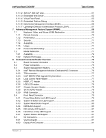
Table of Contents Intel® Server Board S1200V3RP 8.5.3 SATA Connectors 82 8.5.4 Serial Port Connectors 82 8.5.5 USB Connector ...83 8.5.6 I/O Module Connector 84 8.5.7 SAS Module Connector 85 8.5.8 NIC1 with USB2.0 connector 86 8.5.9 NIC2 with USB3.0 connector 87 8.6 Fan Headers ...88 9. BIOS Setup Interface...89 9.1 HotKeys Supported During POST 89 9.2 POST Logo/Diagnostic Screen 89 9.3 BIOS Boot Pop-up Menu 90 9.4 BIOS Setup Utility 90 9.4.1 BIOS Setup Operation 90 9.4.2 BIOS Setup Utility Screens 93 10. Jumper Blocks...195 10.1 BIOS Default Jumper Block 196 10.2 BIOS Recovery Jumper 196 10.3 Password Clear Jumper Block 197 10.4 Management Engine (ME) Firmware Force Update Jumper Block 198 10.5 BMC Force Update Jumper Block 199 11. Intel® Light Guided Diagnostics 200 11.1 System ID LED 201 11.2 System Status LED 201 11.3 BMC Boot/Reset Status LED Indicators 203 11.4 Post Code Diagnostic LEDs 203 11.5 5 Volt Stand-By Present LED 204 12. Environmental Limits Specification 205 12.1 Processor Thermal Design Power (TDP) Support 205 12.2 MTBF ...206 13. Server Board Power Distribution 207 13.1 DC Output Specification 207 13.1.1 Output Power/Currents 207 13.1.2 Cross Loading ...208 13.1.3 Standby Output 208 13.1.4 Voltage Regulation 208 13.1.5 Dynamic Loading 209 13.1.6 Capacitive Loading 209 13.1.7 Grounding ...209 13.1.8 Residual Voltage Immunity in Standy mode 209 13.1.9 Common Mode Noise 210 vi Revision 1.0

  • 1
  • 2
  • 3
  • 4
  • 5
  • 6
  • 7
  • 8
  • 9
  • 10
  • 11
  • 12
  • 13
  • 14
  • 15
  • 16
  • 17
  • 18
  • 19
  • 20
  • 21
  • 22
  • 23
  • 24
  • 25
  • 26
  • 27
  • 28
  • 29
  • 30
  • 31
  • 32
  • 33
  • 34
  • 35
  • 36
  • 37
  • 38
  • 39
  • 40
  • 41
  • 42
  • 43
  • 44
  • 45
  • 46
  • 47
  • 48
  • 49
  • 50
  • 51
  • 52
  • 53
  • 54
  • 55
  • 56
  • 57
  • 58
  • 59
  • 60
  • 61
  • 62
  • 63
  • 64
  • 65
  • 66
  • 67
  • 68
  • 69
  • 70
  • 71
  • 72
  • 73
  • 74
  • 75
  • 76
  • 77
  • 78
  • 79
  • 80
  • 81
  • 82
  • 83
  • 84
  • 85
  • 86
  • 87
  • 88
  • 89
  • 90
  • 91
  • 92
  • 93
  • 94
  • 95
  • 96
  • 97
  • 98
  • 99
  • 100
  • 101
  • 102
  • 103
  • 104
  • 105
  • 106
  • 107
  • 108
  • 109
  • 110
  • 111
  • 112
  • 113
  • 114
  • 115
  • 116
  • 117
  • 118
  • 119
  • 120
  • 121
  • 122
  • 123
  • 124
  • 125
  • 126
  • 127
  • 128
  • 129
  • 130
  • 131
  • 132
  • 133
  • 134
  • 135
  • 136
  • 137
  • 138
  • 139
  • 140
  • 141
  • 142
  • 143
  • 144
  • 145
  • 146
  • 147
  • 148
  • 149
  • 150
  • 151
  • 152
  • 153
  • 154
  • 155
  • 156
  • 157
  • 158
  • 159
  • 160
  • 161
  • 162
  • 163
  • 164
  • 165
  • 166
  • 167
  • 168
  • 169
  • 170
  • 171
  • 172
  • 173
  • 174
  • 175
  • 176
  • 177
  • 178
  • 179
  • 180
  • 181
  • 182
  • 183
  • 184
  • 185
  • 186
  • 187
  • 188
  • 189
  • 190
  • 191
  • 192
  • 193
  • 194
  • 195
  • 196
  • 197
  • 198
  • 199
  • 200
  • 201
  • 202
  • 203
  • 204
  • 205
  • 206
  • 207
  • 208
  • 209
  • 210
  • 211
  • 212
  • 213
  • 214
  • 215
  • 216
  • 217
  • 218
  • 219
  • 220
  • 221
  • 222
  • 223
  • 224
  • 225
  • 226
  • 227
  • 228
  • 229
  • 230
  • 231
  • 232
  • 233
  • 234
  • 235
  • 236
  • 237
  • 238
  • 239
  • 240
  • 241
  • 242
  • 243
  • 244
  • 245
  • 246
  • 247
  • 248
  • 249
  • 250
  • 251
  • 252
  • 253
  • 254
  • 255
  • 256
  • 257
  • 258
  • 259
  • 260
  • 261
  • 262

Table of Contents
Intel® Server Board S1200V3RP
8.5.3
SATA Connectors
................................................................................................
82
8.5.4
Serial Port Connectors
.........................................................................................
82
8.5.5
USB Connector
....................................................................................................
83
8.5.6
I/O Module Connector
..........................................................................................
84
8.5.7
SAS Module Connector
........................................................................................
85
8.5.8
NIC1 with USB2.0 connector
................................................................................
86
8.5.9
NIC2 with USB3.0 connector
................................................................................
87
8.6
Fan Headers
........................................................................................................
88
9.
BIOS Setup Interface
........................................................................................................
89
9.1
HotKeys Supported During POST
........................................................................
89
9.2
POST Logo/Diagnostic Screen
.............................................................................
89
9.3
BIOS Boot Pop-up Menu
......................................................................................
90
9.4
BIOS Setup Utility
................................................................................................
90
9.4.1
BIOS Setup Operation
..........................................................................................
90
9.4.2
BIOS Setup Utility Screens
...................................................................................
93
10.
Jumper Blocks
................................................................................................................
195
10.1
BIOS Default Jumper Block
................................................................................
196
10.2
BIOS Recovery Jumper
......................................................................................
196
10.3
Password Clear Jumper Block
...........................................................................
197
10.4
Management Engine (ME) Firmware Force Update Jumper Block
.....................
198
10.5
BMC Force Update Jumper Block
......................................................................
199
11.
Intel
®
Light Guided Diagnostics
....................................................................................
200
11.1
System ID LED
...................................................................................................
201
11.2
System Status LED
............................................................................................
201
11.3
BMC Boot/Reset Status LED Indicators
.............................................................
203
11.4
Post Code Diagnostic LEDs
...............................................................................
203
11.5
5 Volt Stand-By Present LED
.............................................................................
204
12.
Environmental Limits Specification
..............................................................................
205
12.1
Processor Thermal Design Power (TDP) Support
..............................................
205
12.2
MTBF
.................................................................................................................
206
13.
Server Board Power Distribution
..................................................................................
207
13.1
DC Output Specification
.....................................................................................
207
13.1.1
Output Power/Currents
.......................................................................................
207
13.1.2
Cross Loading
....................................................................................................
208
13.1.3
Standby Output
..................................................................................................
208
13.1.4
Voltage Regulation
.............................................................................................
208
13.1.5
Dynamic Loading
...............................................................................................
209
13.1.6
Capacitive Loading
.............................................................................................
209
13.1.7
Grounding
..........................................................................................................
209
13.1.8
Residual Voltage Immunity in Standy mode
.......................................................
209
13.1.9
Common Mode Noise
.........................................................................................
210
Revision 1.0
vi