Intel P4000RP Technical Product Specification - Page 63
Messaging Interfaces
 |
View all Intel P4000RP manuals
Add to My Manuals
Save this manual to your list of manuals |
Page 63 highlights
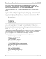
Intel® Server Board S1200V3RP Platform Management Functional Overview Both Static and Dynamic CLTT modes implement a Hybrid Closed Loop Thermal Throttling mechanism whereby the Integrated Memory Controller estimates the DRAM temperature in between actual reads of the memory thermal sensors. 6.11 Messaging Interfaces The BMC supports the following communications interfaces: Host SMS interface by means of low pin count (LPC)/keyboard controller style (KCS) interface Host SMM interface by means of low pin count (LPC)/keyboard controller style (KCS) interface Intelligent Platform Management Bus (IPMB) I2C interface LAN interface using the IPMI-over-LAN protocols Every messaging interface is assigned an IPMI channel ID by IPMI 2.0. The following table shows the standard channel assignments. Table 19. Messaging Interfaces Notes: Channel ID 0 1 2 3 4 5 6 7 8 - 0Dh 0Eh 0Fh Interface Primary IPMB LAN 1 LAN 2 LAN31 (Provided by the Intel® Dedicated Server Management NIC) Reserved USB2 Secondary IPMB SMM Reserved Self3 SMS/Receive Message Queue Supports Sessions No Yes Yes Yes Yes No No No - - No 1. Optional hardware supported by the server system. 2. Reserve USB channel number, current BMC firmware does not support communication through a USB channel. 3. Refers to the actual channel used to send the request. 6.11.1 User Model The BMC supports the IPMI 2.0 user model. 15 user IDs are supported. These 15 users can be assigned to any channel. The following restrictions are placed on user-related operations: 1. User names for User IDs 1 and 2 cannot be changed. These are always "" (Null/blank) and "root" respectively. Revision 1.0 51
-
 1
1 -
2
-
3
-
4
-
5
-
6
-
7
-
8
-
9
-
10
-
11
-
12
-
13
-
14
-
15
-
16
-
17
-
18
-
19
-
20
-
21
-
22
-
23
-
24
-
25
-
26
-
27
-
28
-
29
-
30
-
31
-
32
-
33
-
34
-
35
-
36
-
37
-
38
-
39
-
40
-
41
-
42
-
43
-
44
-
45
-
46
-
47
-
48
-
49
-
50
-
51
-
52
-
53
-
54
-
55
-
56
-
57
-
 58
58 -
 59
59 -
 60
60 -
 61
61 -
 62
62 -
 63
63 -
 64
64 -
 65
65 -
 66
66 -
 67
67 -
 68
68 -
69
-
70
-
71
-
72
-
73
-
74
-
75
-
76
-
77
-
78
-
79
-
80
-
81
-
82
-
83
-
84
-
85
-
86
-
87
-
88
-
89
-
90
-
91
-
92
-
93
-
94
-
95
-
96
-
97
-
98
-
99
-
100
-
101
-
102
-
103
-
104
-
105
-
106
-
107
-
108
-
109
-
110
-
111
-
112
-
113
-
114
-
115
-
116
-
117
-
118
-
119
-
120
-
121
-
122
-
123
-
124
-
125
-
126
-
127
-
128
-
129
-
130
-
131
-
132
-
133
-
134
-
135
-
136
-
137
-
138
-
139
-
140
-
141
-
142
-
143
-
144
-
145
-
146
-
147
-
148
-
149
-
150
-
151
-
152
-
153
-
154
-
155
-
156
-
157
-
158
-
159
-
160
-
161
-
162
-
163
-
164
-
165
-
166
-
167
-
168
-
169
-
170
-
171
-
172
-
173
-
174
-
175
-
176
-
177
-
178
-
179
-
180
-
181
-
182
-
183
-
184
-
185
-
186
-
187
-
188
-
189
-
190
-
191
-
192
-
193
-
194
-
195
-
196
-
197
-
198
-
199
-
200
-
201
-
202
-
203
-
204
-
205
-
206
-
207
-
208
-
209
-
210
-
211
-
212
-
213
-
214
-
215
-
216
-
217
-
218
-
219
-
220
-
221
-
222
-
223
-
224
-
225
-
226
-
227
-
228
-
229
-
230
-
231
-
232
-
233
-
234
-
235
-
236
-
237
-
238
-
239
-
240
-
241
-
242
-
243
-
244
-
245
-
246
-
247
-
248
-
249
-
250
-
251
-
252
-
253
-
254
-
255
-
256
-
257
-
258
-
259
-
260
-
261
-
262
 |
 |
