Intel P4000RP Technical Product Specification - Page 91
Front Panel Connector
 |
View all Intel P4000RP manuals
Add to My Manuals
Save this manual to your list of manuals |
Page 91 highlights
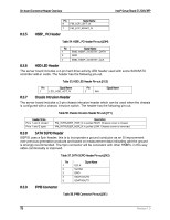
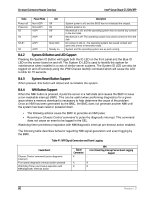
Intel® Server Board S1200V3RP On-board Connector/Header Overview Pin 1 2 3 4 GND P12V FAN_PWM FAN_TACH Signal Name 8.4 Front Panel Connector The server board provides a 24-pin front panel connector (J1E1) for use with Intel® and thirdparty chassis. The connector consists of a 24-pin SSI compatible front panel connector. The 24pin SSI front panel connector provides various front panel features including: Power/Sleep Button System ID Button NMI Button NIC Activity LEDs Hard Drive Activity LEDs System Status LED System ID LED The following table provides the pin-out for this connector: Table 39. Front Panel 24-pin Connector Pin-out (J1E1) Pin 1 3 5 7 9 11 13 15 17 19 21 23 SB3.3V Signal Key Power LED Cathode 3.3V HDD Activity LED Cathode Power Switch GND (Power Switch) Reset Switch GND (Reset/ID/NMI Switch) System ID Switch Pull Down NMI to CPU Switch Pin 2 SB3.3V Signal 4 SB5V 6 System ID LED Cathode 8 System Fault LED Anode 10 System Fault LED Cathode 12 NIC#1 (1/2) Activity LED 14 NIC#1 (1/2) Link LED 16 I2C SDA 18 I2C SCL 20 Chassis Intrusion 22 NIC#2 Activity LED 24 NIC#2 Link LED 8.4.1 Power/Sleep Button and LED Support Pressing the Power button will toggle the system power on and off. This button also functions as a sleep button if enabled by an ACPI compliant operating system. Pressing this button will send a signal to the integrated BMC, which will power on or power off the system. The power LED is a single color and is capable of supporting different indicator states as defined in the following table: Table 40. Power/Sleep LED Functional States State Power Mode LED Description Revision 1.0 79
-
 1
1 -
2
-
3
-
4
-
5
-
6
-
7
-
8
-
9
-
10
-
11
-
12
-
13
-
14
-
15
-
16
-
17
-
18
-
19
-
20
-
21
-
22
-
23
-
24
-
25
-
26
-
27
-
28
-
29
-
30
-
31
-
32
-
33
-
34
-
35
-
36
-
37
-
38
-
39
-
40
-
41
-
42
-
43
-
44
-
45
-
46
-
47
-
48
-
49
-
50
-
51
-
52
-
53
-
54
-
55
-
56
-
57
-
58
-
59
-
60
-
61
-
62
-
63
-
64
-
65
-
66
-
67
-
68
-
69
-
70
-
71
-
72
-
73
-
74
-
75
-
76
-
77
-
78
-
79
-
80
-
81
-
82
-
83
-
84
-
85
-
 86
86 -
 87
87 -
 88
88 -
 89
89 -
 90
90 -
 91
91 -
 92
92 -
 93
93 -
 94
94 -
 95
95 -
 96
96 -
97
-
98
-
99
-
100
-
101
-
102
-
103
-
104
-
105
-
106
-
107
-
108
-
109
-
110
-
111
-
112
-
113
-
114
-
115
-
116
-
117
-
118
-
119
-
120
-
121
-
122
-
123
-
124
-
125
-
126
-
127
-
128
-
129
-
130
-
131
-
132
-
133
-
134
-
135
-
136
-
137
-
138
-
139
-
140
-
141
-
142
-
143
-
144
-
145
-
146
-
147
-
148
-
149
-
150
-
151
-
152
-
153
-
154
-
155
-
156
-
157
-
158
-
159
-
160
-
161
-
162
-
163
-
164
-
165
-
166
-
167
-
168
-
169
-
170
-
171
-
172
-
173
-
174
-
175
-
176
-
177
-
178
-
179
-
180
-
181
-
182
-
183
-
184
-
185
-
186
-
187
-
188
-
189
-
190
-
191
-
192
-
193
-
194
-
195
-
196
-
197
-
198
-
199
-
200
-
201
-
202
-
203
-
204
-
205
-
206
-
207
-
208
-
209
-
210
-
211
-
212
-
213
-
214
-
215
-
216
-
217
-
218
-
219
-
220
-
221
-
222
-
223
-
224
-
225
-
226
-
227
-
228
-
229
-
230
-
231
-
232
-
233
-
234
-
235
-
236
-
237
-
238
-
239
-
240
-
241
-
242
-
243
-
244
-
245
-
246
-
247
-
248
-
249
-
250
-
251
-
252
-
253
-
254
-
255
-
256
-
257
-
258
-
259
-
260
-
261
-
262
 |
 |
