Invacare XLT Owners Manual
Invacare XLT Manual
 |
View all Invacare XLT manuals
Add to My Manuals
Save this manual to your list of manuals |
Invacare XLT manual content summary:
- Invacare XLT | Owners Manual - Page 1
End XLT™ Top End XLT Jr. Top End XLT Pro Top End XLT Gold Top End Force™ DEALER: This manual MUST be given to the user of the handcycle. USER: BEFORE using this handcycle, read this manual and save for future reference. For more information regarding Invacare products, parts, and services, please - Invacare XLT | Owners Manual - Page 2
USE IN CONJUNCTION WITH INVACARE ACCESSORIES. ACCESSORIES DESIGNED BY OTHER MANUFACTURERS HAVE NOT BEEN TESTED BY INVACARE AND ARE NOT RECOMMENDED FOR USE WITH INVACARE PRODUCTS. NOTE: Updated versions of this manual are available on www.invacare.com. Recumbent Handcycle Series 2 Part No 1114850 - Invacare XLT | Owners Manual - Page 3
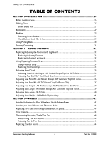
18 Inspect/Adjust Weekly...19 Inspect/Adjust Monthly...20 Inspect/Adjust Periodically...20 Troubleshooting...21 Maintenance ...21 Maintenance Safety Precautions ...21 Suggested Maintenance Procedures 21 SECTION 4-INITIAL SETUP 23 Initial Setup...23 Part No 1114850 3 Recumbent Handcycle Series - Invacare XLT | Owners Manual - Page 4
Models Except Top End XLT Gold 34 Adjusting Top End XLT Gold Hand Crank 35 Adjusting Seat Fore/Aft - All Models Except XLT Gold and Top End Force 36 Adjusting Seat Fore/Aft - XLT Gold and Top End Force In/Toe Out ...45 Replacing Camber Inserts...45 Recumbent Handcycle Series 4 Part No 1114850 - Invacare XLT | Owners Manual - Page 5
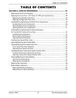
TABLE OF CONTENTS TABLE OF CONTENTS SECTION 8-SERVICE PROCEDURES 46 Replacing the Fork/Crank Assembly ...46 Replacing the Crank Arms - XLT Gold, XLT PRO and Top End Force 49 Replacing the Wide Back Upholstery...59 Replacing Narrow Back Upholstery 59 Part No 1114850 5 Recumbent Handcycle Series - Invacare XLT | Owners Manual - Page 6
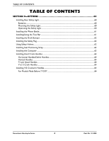
64 Vertical Handles ...64 Tri-pin Quad Handles ...64 V or S Crank Handles ...64 Installing V/S Crankarm Handles...64 For Models Made Before 7/12/07 ...64 Recumbent Handcycle Series 6 Part No 1114850 - Invacare XLT | Owners Manual - Page 7
.invacare.com Please have your model number and purchase date available to complete your registration. Any registration information you submit will only be used by Invacare Corporation and protected as required by applicable laws and regulations. Part No 1114850 7 Excelerator™XLT Handcycle - Invacare XLT | Owners Manual - Page 8
a handcycle. Invacare products are specifically designed and manufactured for use in conjunction with Invacare accessories. Accessories designed by other manufacturers have not been tested by Invacare and are not recommended for use with Invacare products. Recumbent Handcycle Series 8 Part No - Invacare XLT | Owners Manual - Page 9
SPECIAL NOTES ƽ WARNING ALWAYS wear your seat positioning strap. Inasmuch as the seat positioning strap is an option on this handcycle (you may order with or without the seat positioning strap), Invacare strongly recommends ordering the seat positioning strap as an additional safeguard for the - Invacare XLT | Owners Manual - Page 10
XLT TOP END XLT JR Seat Width: 14 to 20 inches 14 inches Seat Depth: 15 inches 15 inches Seat-to-Floor (approx.): 12, 13, or 14 inches 12, 13, or 14 inches Back Style: Adjustable Back Angle 90° - 110° Adjustable Back Angle 90° - 110° Back Height Fixed Towbar for handcycle, Backpack - Invacare XLT | Owners Manual - Page 11
Bottle and Cage, Fixed seat frame, Alignment Gauge, Backpack Hydration System, Carbon Fiber Wheels, Crutch Holder, Drafting Bumper, Titanium Parts, Indoor Training Roller *NOTE: Knobby tires will reduce side wheel clearance to approximately 1‐inch. Part No 1114850 11 Recumbent Handcycle Series - Invacare XLT | Owners Manual - Page 12
flat against footrest hoop. • XLT Series requires a 18ʹ handcycle on level ground and as close as possible to the object you are transferring into or out of. The object you are transferring into or out of MUST also be secured before attempting any transfer. Recumbent Handcycle Series 12 Part - Invacare XLT | Owners Manual - Page 13
GUIDELINES Top End XLT, XLT jr., and XLT Gold Models Only ‐ The parking brake of the handcycle MUST be engaged before attempting any transfer. Top End XLT Pro Model Only ‐ This model may be ordered with or without a parking brake. If ordered without a parking brake, the handcycle MUST be positioned - Invacare XLT | Owners Manual - Page 14
GENERAL GUIDELINES Tire Pressure DO NOT use your handcycle unless it has the proper tire pressure (p.s.i.). cause injury, as well as, damage to the tire, tube and handcycle. Weight Limitation The Invacare Top End XLT handcycles have a weight limitation of 250 lbs. A weight limitation label is on - Invacare XLT | Owners Manual - Page 15
the handcycle. Use this information only as a basic guide. The techniques that are discussed on the following pages have been used successfully by many. Individual users often develop skills to deal with daily living activities that may differ from those described in this manual. Invacare recognizes - Invacare XLT | Owners Manual - Page 16
attempting any transfer. TOP END XLT, XLT JR. AND XLT GOLD MODELS ONLY - The parking brake of the handcycle MUST be engaged before attempting any transfer. TOP END XLT PRO MODEL ONLY - This model may locks (if installed) if the object is a handcycle. Recumbent Handcycle Series 16 Part No 1114850 - Invacare XLT | Owners Manual - Page 17
handcycle seat. STEP D: Place RIGHT hand on the wheelchair frame. STEP C: Place LEFT hand on the left side of handcycle seat frame, wheelchair. Refer to the steps on the previous page for more information. NOTE: Handcycle shown for clarity. FIGURE 2.1 Transferring Into/Out of the Handcycle Part - Invacare XLT | Owners Manual - Page 18
servicing. Regular cleaning will reveal loose or worn parts and enhance the smooth operation of your Top End XLT. For safe and proper operation, your handcycle MUST be cared for just like any other vehicle. Routine maintenance will extend the life and efficiency of your Top End XLT. NOTE: Invacare - Invacare XLT | Owners Manual - Page 19
latches. Verify hardware that attaches strap to frame is secure and undamaged. Replace if necessary to shifter/brake manufacturerʹs instructions (included with the handcycle). ❑ Inspect front fork latches. Verify hardware that attaches strap to frame is secure and undamaged. Replace if necessary. - Invacare XLT | Owners Manual - Page 20
brake cables according to shifter/brake manufacturerʹs instructions (included with the handcycle). ❑ Inspect front fork. Keep tight wear. Ensure buckle latches. Verify hardware that attaches strap to frame is secure and undamaged. Replace if necessary. ❑ Inspect Handcycle Series 20 Part No 1114850 - Invacare XLT | Owners Manual - Page 21
Troubleshooting SECTION 3-SAFETY INSPECTION VEERS VEERS SLUGGISH WHEEL SQUEAKS LOOSENESS IN SOLUTIONS RIGHT LEFT TURN OR FLUTTERS AND HANDCYCLE PERFORMANCE RATTLES X X X X Check tires for correct and equal pressure. X X Check road crown compensator or XLT Gold dampener hardware and - Invacare XLT | Owners Manual - Page 22
the Road Crown Compensator on page 50 and Installing/Removing/Adjusting the Steering Dampener ‐ For Top End XLT Gold and Force Only on page 52. 11. Check upholstery for sagging, rips or tears. Refer to hand, have it aligned at your local bicycle shop. Recumbent Handcycle Series 22 Part No 1114850 - Invacare XLT | Owners Manual - Page 23
Force on page 36, Adjusting Seat Height ‐ All Models Except XLT Gold and Top End Force on page 38 and/or Replacing Seat Upholstery on page 58). 9. Adjust the hand crank. Refer to Adjusting Hand Crank on page 34. 10. Check that all hardware is tight. Part No 1114850 23 Recumbent Handcycle Series - Invacare XLT | Owners Manual - Page 24
Location Chain Parking Brake Cable Footrest Back Rear Wheel NOTE: Parking brake located on left side of seat frame. Top End XLT PRO Hand Crank Assembly Brake Cable Fork Mounted Shifters and Brakes Chain Seat Footrest FIGURE 4.1 Initial Setup Recumbent Handcycle Series 24 Part No 1114850 - Invacare XLT | Owners Manual - Page 25
Top End XLT Gold Hand Crank Assembly Back Seat SECTION 4-INITIAL SETUP Rapid-Fire Hand Brake/Shifter Chain Footrest Rear Wheel Top End Force Hand Crank Assembly Back Rapid-Fire Hand Brake/Shifter Chain Seat FIGURE 4.2 Initial Setup Footrest Part No 1114850 25 Recumbent Handcycle Series - Invacare XLT | Owners Manual - Page 26
, repair or service and before use, make sure all attaching hardware is tightened securely - otherwise injury or damage may result. Riding the Handcycle ƽ WARNING Before operating the handcycle, review the General Guidelines on page 12 in of this manual. DO NOT operate the handcycle if the hand - Invacare XLT | Owners Manual - Page 27
End XLT shown for clarity. Hand Crank (STEPS 3, 6, 8 and 9) Top End XLT and XLT Jr. ONLY Seat (STEP 5) Rear of Handcycle Front of Handcycle Footrest (STEP 4) FIGURE 5.1 Riding the Handcycle Shifting FIGURE 5.2 Shifting Gears - Seven Speed Hub Part No 1114850 27 Recumbent Handcycle Series - Invacare XLT | Owners Manual - Page 28
End XLT Pro, XLT Gold, and Force ONLY. To shift gears, you MUST turn the crank forward with the chain under some tension while the bike is moving. DO NOT attempt to shift gears while bike is stationary. There are two shifters installed on the handcycle handcycle MANUAL Manual handcycle - Invacare XLT | Owners Manual - Page 29
like a manual handcycle) to backup. When backing up, keep the front wheel straight. The weight of the hand crank may engage the reversing drum brakes (Top End XLT and XLT jr. models ONLY) while backing up. Lift the pedals up to avoid this problem. CAUTION If backing up in the XLT PRO, XLT Gold and - Invacare XLT | Owners Manual - Page 30
XLT Pro, XLT Gold and Top End Force models use the hand brake as the primary brake. Reverse pedaling WILL NOT stop the bike. Handcycles handcycle, every precaution should be taken to reduce the gap distance. Position the handcycle The parking brake of the handcycle MUST be engaged before attempting - Invacare XLT | Owners Manual - Page 31
Handle NOTE: Approximate location shown. Actual side of handcycle and location on seat frame may vary. FIGURE 5.5 Using Parking Brake Steering/Cornering When cornering, it is recommended that you slow the handcycle, stop pedaling, steer the handcycle and coast through the turn. Hands should be up in - Invacare XLT | Owners Manual - Page 32
ƽ WARNING After any adjustments, repair or service and before use, make sure all attaching Leg Guard Front Tire NOTE: This procedure is for Top End XLT, XLT Jr., and XLT Pro ONLY. 1. Loosen the two allen screws on each mounting clamp securely. Recumbent Handcycle Series 32 Part No 1114850 - Invacare XLT | Owners Manual - Page 33
feet in using straps provided. Severe injury may occur if feet are not secured while the handcycle is in motion. Using Footrest Strap NOTE: For this procedure, refer to FIGURE 6.2. Loop Fastening Strip (STEP 6) FIGURE 6.3 Replacing Footrest Strap Part No 1114850 33 Recumbent Handcycle Series - Invacare XLT | Owners Manual - Page 34
handcycle - otherwise injury or damage may occur. Adjusting Hand Crank Height - All Models Except Top End XLT Gold when the hand is toward the front of the handcycle, the arm is slightly bent. The arm should Hand Crank Height All Models Except Top End XLT Gold 3. Tighten the hex nut to secure the - Invacare XLT | Owners Manual - Page 35
SECTION 6-RIDING POSITION Adjusting Top End XLT Gold Hand Crank NOTE: For this procedure, refer to FIGURE 6.5. Adjusting Hand Crank Height 1. Loosen, and Set Screws Hand Crank (Gear and Chain Not Shown) FIGURE 6.5 Adjusting Top End XLT Gold Hand Crank Part No 1114850 35 Recumbent Handcycle Series - Invacare XLT | Owners Manual - Page 36
. Back Support Tube Seat Angle Adjustment Clamps Height Adjustment Clamp Front Socket Screw Rear Socket Screws Handcycle Frame Height Adjustment Bracket Seat Frame FIGURE 6.6 Adjusting Seat Fore/Aft - All Models Except XLT Gold and Top End Force Recumbent Handcycle Series 36 Part No - Invacare XLT | Owners Manual - Page 37
SECTION 6-RIDING POSITION Adjusting Seat Fore/Aft - XLT Gold and Top End Force Only NOTE: For this procedure, refer to FIGURE 6.7. . Mounting Bolt and Locknut Seat Rails Back Clamp FIGURE 6.7 Adjusting Seat Fore/Aft - XLT Gold and Top End Force Only Part No 1114850 37 Recumbent Handcycle Series - Invacare XLT | Owners Manual - Page 38
frame. Back Support Tube Seat Angle Adjustment Clamps Height Adjustment Clamp Front Socket Screw Rear Socket Screws Handcycle Frame Height Adjustment Bracket Seat Frame FIGURE 6.8 Adjusting Seat Height - All Models Except XLT Gold and Top End Force Recumbent Handcycle Series 38 Part - Invacare XLT | Owners Manual - Page 39
bolts and locknuts that secure the two seat angle adjustment clamps to the rear seat supports securely. Back Support Tube Seat Angle Adjustment Clamps Rear Socket Screws Handcycle Frame FIGURE 6.9 Adjusting Back Angle - All Models Except XLT Gold and Top End Force Part No 1114850 39 Recumbent - Invacare XLT | Owners Manual - Page 40
upward to the desired position. 3. Securely tighten the two socket screws located in the seat angle adjustment clamp. Back Support Tube Socket Screw Adjustment Holes NOTE: Wheel not shown for clarity. FIGURE 6.10 Adjusting Back Angle - XLT Gold Recumbent Handcycle Series 40 Part No 1114850 - Invacare XLT | Owners Manual - Page 41
This procedure applies to Top End XLT models with wide back option only. 1. Remove the back upholstery from the handcycle. Refer to Replacing Back Upholstery on on original back height. 3. Reinstall the back upholstery onto the handcycle. Refer to Replacing Back Upholstery on page 59. Back Cane Push - Invacare XLT | Owners Manual - Page 42
handcycle. 6. Tilt handcycle onto either rear wheel and spin raised wheel. It should spin freely with no excessive drag. 7. Repeat procedure for opposite rear wheel. NOTE: If drag to either side occurs, repeat the procedure until the handcycle rolls correctly. Recumbent Handcycle Series 42 Part - Invacare XLT | Owners Manual - Page 43
Allen Wrench Frame Rear Wheel Axle FIGURE 7.2 Installing the Rear Wheels with Threaded Axles Replacing Tire/Tube and Tuning/Replacement of Spokes NOTE: Invacare recommends that these procedures be performed by a qualified technician. Tire Pressure ƽ WARNING DO NOT use the handcycle unless it has - Invacare XLT | Owners Manual - Page 44
greater than 1/8‐inch (for maximum rollability), one of two conditions exists: Top View of handcycle • If the back centerline measurement of the rear wheels is smaller than the front centerline Screw FIGURE 7.3 Determining/Adjusting Toe In/Toe Out Recumbent Handcycle Series 44 Part No 1114850 - Invacare XLT | Owners Manual - Page 45
the existing camber insert from the camber bar. 3. Install the new camber insert into the camber bar. 4. Adjust the toe in/toe out of the handcycle. Refer to Determining/Adjusting Toe In/Toe Out on page 44. Clamp Camber Camber Bar Insert Socket Screw - Invacare XLT | Owners Manual - Page 46
position of the footrests and remove the footrests from the existing fork. 17. Remove the two top nuts that secure the existing fork to the frame. 18. Note the o‐ring and bearing position and remove the existing fork from the frame. Recumbent Handcycle Series 46 Part No 1114850 - Invacare XLT | Owners Manual - Page 47
SECTION 8-SERVICE PROCEDURES 19. Slide the bottom bearing onto the new fork. Refer to FIGURE 8.1 for correct orientation. 20. Slide the new fork into the frame. 21. Position the o‐ring and bearing on the 1 and tighen the two socket screws securely. Part No 1114850 47 Recumbent Handcycle Series - Invacare XLT | Owners Manual - Page 48
SECTION 8-SERVICE PROCEDURES STEPS 1, 2, 3, 36, 37 Socket Screws Fork Crank Handle STEPS 6, 7, 34 5, 17, 18, 19, 20, 21, 22, 35 Top Nuts Crank Handle Bearing O-Ring Frame Frame Fork Bottom Bearing FIGURE 8.1 Replacing the Fork/Crank Assembly Recumbent Handcycle Series 48 Part No 1114850 - Invacare XLT | Owners Manual - Page 49
SERVICE PROCEDURES Replacing the Crank Arms - XLT Gold, XLT PRO and Top End Force NOTE: For this procedure, refer to FIGURE 8.2 on page 50. NOTE: Right and left determined from as if seated on the handcycle arm clamp to the spindle. Securely tighten. Part No 1114850 49 Recumbent Handcycle Series - Invacare XLT | Owners Manual - Page 50
FIGURE 8.2 Replacing the Crank Arms - XLT Gold, XLT PRO and Top End Force Installing/Removing/Adjusting the Road Crown Compensator NOTE: For this procedure, refer to FIGURE 8.3 on page 51. NOTE: The road crown compensator is designed to stabilize the handcycle during transfers and while riding and - Invacare XLT | Owners Manual - Page 51
Road Crown Compensator Fork Bolt Removed Locknut Installed Frame Frame Frame Mounting Hole Fork End Fork Road Crown Compensator Road Crown Compensator Frame End Bolt Spacer FIGURE 8.3 Installing/Removing/Adjusting the Road Crown Compensator Part No 1114850 51 Recumbent Handcycle Series - Invacare XLT | Owners Manual - Page 52
SECTION 8-SERVICE PROCEDURES Installing/Removing/Adjusting the Steering Dampener For Top End XLT Gold and Force Only NOTE: For this procedure, refer to FIGURE 8.4 on page 53. NOTE: The steering dampener is designed to stabilize the handcycle during transfers and while riding and is not intended to - Invacare XLT | Owners Manual - Page 53
XLT Gold ONLY Crank Assembly Tab Upper Threaded Post and Locknut SECTION 8-SERVICE PROCEDURES Socket Screws (One Located on Both Sides of the Handcycle Frame) Steering Dampener Top End Force ONLY Lower Threaded Post and Locknut Upper Threaded Post and Locknut Steering Dampener Handcycle Frame - Invacare XLT | Owners Manual - Page 54
serviced and adjusted by a qualified technician. NOTE: QUALIFIED TECHNICIANS ONLY ‐ Contact Invacare, 1‐800‐532‐8677 for complete SHIMANO hub instructions. It is recommended that you take your handcycle FIGURE 8.6 Seven Speed Hub Chain Installation Recumbent Handcycle Series 54 Part No 1114850 - Invacare XLT | Owners Manual - Page 55
procedure, refer to FIGURE 8.7 on page 55. NOTE: This procedure applies to the Top End XLT and Top End XLT Jr. only. 1. Ensure the hand crank is adjusted to the proper height. Refer to Adjusting Hand . 4. Thread the chain around the wheel sprocket. Part No 1114850 55 Recumbent Handcycle Series - Invacare XLT | Owners Manual - Page 56
SECTION 8-SERVICE PROCEDURES 5. Run the chain around the bottom of the wheel sprocket and back up towards the hand crank sprocket. should be performed by a qualified technician. 3. Tighten the clamp that secure the crank handles to the fork securely. Recumbent Handcycle Series 56 Part No 1114850 - Invacare XLT | Owners Manual - Page 57
Handle SECTION 8-SERVICE PROCEDURES Fork Clamps FIGURE 8.9 Adjusting Twenty-Seven Speed Cassette Chain Adjusting/Replacing the Parking Brake ƽ WARNING Before using your handcycle, inspect the brake pads. 2. Secure with existing hardware and adjust. Part No 1114850 57 Recumbent Handcycle Series - Invacare XLT | Owners Manual - Page 58
SECTION 8-SERVICE PROCEDURES Parking Brake ƽ WARNING Replacement of the parking brake MUST be of Seat Frame Back Upholstery Three Seat Upholstery Fastening Straps Towards Rear of Seat Frame Towards Front of Chair FIGURE 8.11 Replacing Seat Upholstery Recumbent Handcycle Series 58 Part No - Invacare XLT | Owners Manual - Page 59
Flap Fastening Flap Back Cane FIGURE 8.12 Replacing Wide Back Upholstery Fastening Strips Back Frame Fixed Seat Narrow Back Back Cushion Fastening Strips Back Frame Adjustable Seat Narrow Back FIGURE 8.13 Replacing Narrow Back Upholstery Part No 1114850 59 Recumbent Handcycle Series - Invacare XLT | Owners Manual - Page 60
or service and before use, make sure all attaching hardware is tightened securely - otherwise injury or damage may result. Installing Rear Safety Light ƽ WARNING Operation of the handcycle is slide switch back and forth for pulse or constant mode. Recumbent Handcycle Series 60 Part No 1114850 - Invacare XLT | Owners Manual - Page 61
to the handcycle rear frame. Mounting Bracket 4. Secure the tow bar to the handcycle with the mounting brackets and set screws. Set Screws Handcycle Rear Frame 5. Secure the wheelchair to the tow bar with the fastening strips provided. FIGURE 9.3 Installing/Using the Tow Bar Part No 1114850 - Invacare XLT | Owners Manual - Page 62
bike frame. Safety Flag Back Tube Holder FIGURE 9.5 Installing the Safety Flag Using Safety Helmet NOTE: For this procedure, refer to FIGURE 9.6. 1. Secure helmet using the chin strap. 2. Ensure proper fit. Helmet FIGURE 9.6 Using Safety Helmet Recumbent Handcycle Series 62 Part No 1114850 - Invacare XLT | Owners Manual - Page 63
screws and attach the computer mounting bracket. 5. Snap computer into mounting bracket. Computer Sensor Mounting Bracket Front Wheel Spoke Metal Plug FIGURE 9.8 Installing the Computer Part No 1114850 63 Recumbent Handcycle Series - Invacare XLT | Owners Manual - Page 64
: For this procedure, refer to FIGURE 9.10 on page 65. 1. Secure the handle to the crankarm housing using the bolt, spacer, and two bearings. Recumbent Handcycle Series 64 Part No 1114850 - Invacare XLT | Owners Manual - Page 65
firmly in place. If handle still does not spin freely, contact Invacare. Bolt Bearing Crankarm Housing Bearing Spacer Crankarm Handle FIGURE 9.10 Installing minimal play. If handle does not spin freely, contact Invacare. DETAIL "B" - CRANKARM ORIENTATION Left Handle Mounting Post Right - Invacare XLT | Owners Manual - Page 66
9.13 Mountain Drive Transmission Option Mountain Drive Transmission Option Maintenance The mountain drive transmission option should be maintained by a qualified technician according to the manufacturerʹs instructions included with the handcycle. Recumbent Handcycle Series 66 Part No 1114850 - Invacare XLT | Owners Manual - Page 67
camber bar. 3. Slide the camber bar through the clamps. Seat Support Clamp (Not Present on XLT Gold) Seat Support Clamp (Not Present on XLT Gold) Camber Bar Socket Screws Frame Clamp Socket Screws FIGURE 9.14 Removing/Installing the Camber Bar Part No 1114850 67 Recumbent Handcycle Series - Invacare XLT | Owners Manual - Page 68
Ready XLT PRO Equipped of the fork. 5. Remove the fork from the frame. 6. Remove the front wheel from the fork.Refer to handcycle, if handcycle pulls to the left or right adjust the road crown compensator. Refer to Adjusting Road Crown Compensator on page 51. Recumbent Handcycle Series 68 Part - Invacare XLT | Owners Manual - Page 69
Clamp Fork Fork Clamp Plate SECTION 9-OPTIONS Frame Fork Clamps Nut Fork Bolt Road Crown Compensator FIGURE 9.15 Removing/Installing the Fork - Travel Ready XLT PRO Equipped with Road Crown Compensator Removing/Installing the Fork - XLT Gold, and Top End Force Equipped with Steering Dampener - Invacare XLT | Owners Manual - Page 70
Handcycle Frame Fork Clamp Fork FIGURE 9.16 Removing/Installing the Fork - XLT Gold, and Top End Force Equipped with Steering Dampener Removing/Installing the Front Wheel - XLT Gold, XLT Pro and XLT the fork. 4. Remove the chain from the front wheel. Recumbent Handcycle Series 70 Part No 1114850 - Invacare XLT | Owners Manual - Page 71
Wheel NOTE: For ease of installation, secure handcycle frame approximately 6 inches from the ground or seek Installing the Front Wheel - XLT Gold, XLT Pro and XLT with Speed Cassette Chain Assembling/Using/Adjusting the Handcycle Rack NOTE: For this Part No 1114850 71 Recumbent Handcycle Series - Invacare XLT | Owners Manual - Page 72
the vehicle manufacturerʹs instructions. Using the Handcycle Rack 1. Position the handcycle on the rack with the front wheel in the wheel tray bracket. 2. Adjust the handcycle rack so the wheel FIGURE 9.18 Assembling/Using/Adjusting the Handcycle Rack Recumbent Handcycle Series 72 Part No 1114850 - Invacare XLT | Owners Manual - Page 73
Repeat STEPS 1‐3 for the opposite side if necessary. Rear Wheel Bar NOTE: To properly secure the handcycle, the rear wheel bar should be adjusted so the rear wheels sit in the rear wheel bar brackets. tray with the two mounting bolts and locknuts. Part No 1114850 73 Recumbent Handcycle Series - Invacare XLT | Owners Manual - Page 74
. Refer to Adjusting Toe In/Toe Out on page 45. Alignment Gauge Alignment Bar Alignment Screw Front of Handcycle Rear Tires Front Measurement Height Alignment Screw Rear Measurement Rear of Handcycle FIGURE 9.19 Using the Alignment Gauge Recumbent Handcycle Series 74 Part No 1114850 - Invacare XLT | Owners Manual - Page 75
, OR TO A PRODUCT DAMAGED BY CIRCUMSTANCES BEYOND INVACARE'S CONTROL, AND SUCH EVALUATION WILL BE SOLELY DETERMINED BY INVACARE. THE WARRANTY SHALL NOT APPLY TO PROBLEMS ARISING FROM NORMAL WEAR OR FAILURE TO ADHERE TO THESE INSTRUCTIONS. THE FOREGOING EXPRESS WARRANTY IS EXCLUSIVE AND IN LIEU - Invacare XLT | Owners Manual - Page 76
are identified by the symbols ™ and ®. All trademarks are owned by or licensed to Invacare Corporation unless otherwise noted. Shimano, Nexus, and Ultegra are registered trademarks of Shimano Inc 242 is a trademark of the Loctite Corporation. © 2007 Invacare Corporation Part No 1114850 Rev D- 07/07
-
 1
1 -
 2
2 -
 3
3 -
 4
4 -
 5
5 -
 6
6 -
 7
7 -
8
-
9
-
10
-
11
-
12
-
13
-
14
-
15
-
16
-
17
-
18
-
19
-
20
-
21
-
22
-
23
-
24
-
25
-
26
-
27
-
28
-
29
-
30
-
31
-
32
-
33
-
34
-
35
-
36
-
37
-
38
-
39
-
40
-
41
-
42
-
43
-
44
-
45
-
46
-
47
-
48
-
49
-
50
-
51
-
52
-
53
-
54
-
55
-
56
-
57
-
58
-
59
-
60
-
61
-
62
-
63
-
64
-
65
-
66
-
67
-
68
-
69
-
70
-
71
-
72
-
73
-
74
-
75
-
76
 |
 |

Owner’s Operator and Maintenance Manual
DEALER:
This manual MUST be given to
the user of the handcycle.
USER:
BEFORE using this handcycle, read
this manual and save for future reference.
For more information regarding
Invacare products,
parts, and services,
please visit www.invacare.com
Recumbent
Handcycle Series
Top End XLT™
Top End XLT Jr.
Top End XLT Pro
Top End XLT Gold
Top End Force™
®