Invacare XLT Owners Manual - Page 74
Using the Alignment Gauge
 |
View all Invacare XLT manuals
Add to My Manuals
Save this manual to your list of manuals |
Page 74 highlights
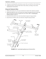
SECTION 9-OPTIONS Using the Alignment Gauge NOTE: For this procedure, refer to FIGURE 9.19. NOTE: The alignment gauge is used to determine toe in/toe out. Refer to Determining/Adjusting Toe In/Toe Out on page 44 for more information. 1. Inflate all pneumatic tires to recommended tire pressures (listed on the sidewall of the tire). 2. Place the handcycle and alignment gauge on a flat surface. 3. Position the alignment gauge near the rear of the rear tires. 4. Loosen the height adjustment screw. 5. Raise/lower the alignment bar so the bar is approximately 12 inches from the ground/floor. 6. Tighten the height adjustment screw. 7. Loosen the alignment screw. 8. Position the alignment gauge between the rear of the rear tires. 9. Adjust the alignment bar so the alignment gauge fits snugly between the rear of the rear tires. 10. Tighten the alignment screw to secure the alignment bar position. 11. Position the alignment gauge at the front of the rear tires. 12. Examine the gauge. Perform one of the following: A. Alignment Gauge Fits Snugly Between the Front of the Rear Tires ‐ Wheels are aligned. No toe in/toe out adjustment is needed. B. There is Extra Space Between the Alignment Gauge and Rear Tires ‐ The tires have a toe out condition. Refer to Adjusting Toe In/Toe Out on page 45. C. Alignment Gauge Does Not Fit Between Rear Tires ‐ The tires have a toe in condition. Refer to Adjusting Toe In/Toe Out on page 45. Alignment Gauge Alignment Bar Alignment Screw Front of Handcycle Rear Tires Front Measurement Height Alignment Screw Rear Measurement Rear of Handcycle FIGURE 9.19 Using the Alignment Gauge Recumbent Handcycle Series 74 Part No 1114850
-
 1
1 -
2
-
3
-
4
-
5
-
6
-
7
-
8
-
9
-
10
-
11
-
12
-
13
-
14
-
15
-
16
-
17
-
18
-
19
-
20
-
21
-
22
-
23
-
24
-
25
-
26
-
27
-
28
-
29
-
30
-
31
-
32
-
33
-
34
-
35
-
36
-
37
-
38
-
39
-
40
-
41
-
42
-
43
-
44
-
45
-
46
-
47
-
48
-
49
-
50
-
51
-
52
-
53
-
54
-
55
-
56
-
57
-
58
-
59
-
60
-
61
-
62
-
63
-
64
-
65
-
66
-
67
-
68
-
 69
69 -
 70
70 -
 71
71 -
 72
72 -
 73
73 -
 74
74 -
 75
75 -
 76
76
 |
 |
