JVC BR-DV3000UB BR-DV3000U Pro-DV recorder 71 page instruction manual - Page 22
Connection, Setting up this unit, Operation, Setting
 |
UPC - 046838325595
View all JVC BR-DV3000UB manuals
Add to My Manuals
Save this manual to your list of manuals |
Page 22 highlights
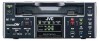
RECORDING - Backup recording function - By linking this unit to other DV devices, this unit can perform continuous, long-hour recording. This unit can be set as a backup unit connected to a DV camcorder (GY-DV300/DV500/DV550/ DV5000, etc.). When the recording tape of the source unit ends, this unit can start recording. This enables long-hour recording. Backup unit: the main unit FILTER 1 3200k 2 5600k 3 5600k+ND SHUTTER STATUS MENU ALARM MONITOR AUTO IRIS FULL AUTO BLACK BACK L NORMAL SPOT L STRETCH NORMAL COMPRESS LOLUX PRST A B ON KNEE OFF AUTO BARS CAM HML SAVE STBY VTR GAIN OUTPUT WHT.BAL NG POWER ON OFF OPERATE/WARNING RESET MONITOR SELECT CH-1 AUDIO CH-2 LEVEL LIGHT ON OFF COUNTER CTL TC UB DV cable DV terminal OPERATE DV terminal Mini A.DUB PROFESSIONAL MIC REMOTE SEL. INPUT SEL. SERIAL LINE 9PIN WIRELESS DV Y/C DVCAM NTSC PAL REC INH. CH-1/3 CH-2/4 BR-DV3000 EJECT MENIU REC PLAY PAUSE SET REW STOP FF INPUT SEL. switch Connection Connect the DV terminal of the source unit to the DV terminal of this unit with a DV cable. Setting up this unit Ⅵ Set the INPUT SEL. switch on the front panel to DV. Ⅵ Set the BACKUP REC TIME item of the SYSTEM (1/2) menu. Use the following settings according to the length of the tape of the source unit. For DV or mini DV cassettes: 25MIN 55MIN 75MIN : 30-minute tape : 60-minute tape : 80-minute tape 115MIN 175MIN 265MIN OFF : 120-minute tape : 180-minute tape : 270-minute tape : No backup recording Ⅵ Set the TC DUPLICATE item of the TIME CODE menu to OFF. • It records the data of the built-in time code generator or the built-in clock. • When the TC DUPLICATE menu item is set to AUTO or NON DROP, the time code of the DV camcorder will stop advancing. If the DV cable is disconnected, the time code of the backup recording will stop advancing. Operation 1. Recording begins on the source unit. * Please record from the beginning of the recording tape. 2. This unit begins recording when the tape of the source unit is near the end (about 5 minutes before the end of the tape). • This unit begins recording when the recording time of the source unit reaches the time configured by the BACKUP REC TIME setting. Memo • Backup recording records the video and sound from the source unit to the main unit. While this unit is performing backup recording, please continue shooting from the source unit. • The audio mode is the mode configured in the source unit. (32k/48k) • Please set the BACKUP REC TIME item to OFF if the unit is not performing backup recording. 40 RECORDING - Recording using the serial remote terminal - Recording can be turned ON/OFF with the serial remote controller or the footswitch connected to the SERIAL REMOTE terminal on the rear panel. SERIAL REMOTE terminal OPERATE Mini A.DUB PROFESSIONAL MIC REMOTE SEL. INPUT SEL. SERIAL LINE 9PIN WIRELESS DV Y/C DVCAM NTSC PAL REC INH. CH-1/3 CH-2/4 BR-DV3000 EJECT MENIU REC PLAY PAUSE SET REW STOP FF DV IN/OUT AUDIO CH 1/3 CH 2/4 LINE VIDEO Y/C OUT IN REMOTE DC12V NTSC/PAL 9PIN SERIAL NTSC PAL REMOTE SEL. switch • Serial remote controller: RM-G30 • Footswitch REMOTE (1/2) menu - - - REMOT E [ 1 / 2 ] - - - REMOT E LOCA L FUNCT I ON PREROL L REM F F / REW MOD E REM STOP SEL PB START DELAY SYNCHRON I ZAT I ON NEXT PAGE PAGE BACK ON ALL KEYS 5S F F / REW EE OF ON Memo • The serial remote controller can perform operations other than recording. • The buttons on the unit to be rendered operable can be set via the LOCAL FUNCTION item of the REMOTE(1/2) menu. REMOTE (2/2) menu - - - REMOT E [ 2 / 2 ] - - - CONTROL L ER SE L TYPE 1 FOOT SW OFF PAGE BACK Connection Connect the serial remote controller (available separately: RM-G30) or the footswitch to the SERIAL REMOTE terminal on the rear panel. Setting Ⅵ Set the REMOTE SEL. switch on the front panel to SERIAL. Ⅵ Set the REMOTE item of the REMOTE (1/2) menu to ON. Ⅵ Set the FOOT SW item of the REMOTE (2/2) menu according to the way in which the serial remote terminal is used. OFF L EDGE H EDGE L LEVEL : Set to OFF when the serial remote controller is used. The footswitch cannot be used. : Recording and recording pause operations are switched at the LOW edge of the footswitch signal. : Recording and recording pause operations are switched at the HIGH edge of the footswitch signal. : Record at the LOW edge and pause recording at the HIGH edge of the footswitch signal. Operation Before using the footswitch, first engage the recording or recording pause mode via the buttons on the main unit. Memo • The footswitch can only be used for switching the recording operation ON/OFF. • The footswitch functions irrespectively of the REMOTE SEL switch settings. 41
-
 1
1 -
2
-
3
-
4
-
5
-
6
-
7
-
8
-
9
-
10
-
11
-
12
-
13
-
14
-
15
-
16
-
 17
17 -
 18
18 -
 19
19 -
 20
20 -
 21
21 -
 22
22 -
 23
23 -
 24
24 -
 25
25 -
 26
26 -
 27
27 -
28
-
29
-
30
-
31
-
32
-
33
-
34
-
35
-
36
-
37
 |
 |
