JVC BR-DV3000UB BR-DV3000U Pro-DV recorder 71 page instruction manual - Page 9
Rear panel
 |
UPC - 046838325595
View all JVC BR-DV3000UB manuals
Add to My Manuals
Save this manual to your list of manuals |
Page 9 highlights
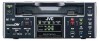
NAMES AND FUNCTIONS OF VARIOUS PARTS - Rear panel - DV IN/OUT AUDIO CH 1/3 CH 2/4 LINE VIDEO Y/C OUT IN REMOTE DC12V NTSC/PAL 9PIN SERIAL NTSC PAL 1 4 32 1 DC power input terminal (2P) This is used for DC12V input. It connects the DC power cord of the provided AC adapter. Memo ● When power is supplied to this terminal, the OPERATE indicator located at the front panel lights up. (The LED lights up red when the OPERATE indicator is OFF.) ● Setting this unit to OPERATE ON, OPERATE OFF or PLAY mode when the power is supplied to this terminal can be done by making the appropriate selections from the DC IN MODE item in the SYSTEM menu. 2 [NTSC/PAL] NTSC/PAL signal se- lection switch Use this switch to select NTSC or PAL as the signal system. Use it to make a selection when composite video signals or YC separate video signals are input. NTSC : Use this setting for NTSC signal input. The NTSC indicator on the front panel lights up. PAL : Use this setting for PAL signal input. 3 [SERIAL REMOTE] serial remote terminal (mini jack) Connect this terminal to the serial remote controller RM-G30, which is available separately. To control this unit via this terminal, please set it up as follows. ● Set the REMOTE item of the REMOTE menu to ON. ● Set the [REMOTE SEL.] switch on the front panel to "SERIAL". Memo To use this terminal as the FOOT switch input terminal, please set the FOOTSW item of the REMOTE (2/2) menu. ☞ Page 60 4 [9 PIN REMOTE] 9-pin remote ter- minal (D-SUB) Use this terminal to connect to the RS-422Acompatible editing remote controller (RM-G820). Please use this unit as a player. To control this unit with this terminal, please set it up as follows: ● Set the REMOTE item of the REMOTE menu to ON. The PAL indicator on the front panel lights up. ● Set the [REMOTE SEL.] switch on the front panel to "9 PIN". Memo ● For playback or DV signal input, signals are determined automatically and not affected by the status of this switch. ● Please turn the unit to OPERATE OFF before using this switch. If switching is performed when the VTR is in the OPERATE ON mode, the VTR will automatically go into the OFF mode before engaging the ON mode. ● It cannot be used for NTSC/PAL conversion. 14 ! 65 9 0 DV IN/OUT AUDIO CH 1/3 CH 2/4 LINE VIDEO Y/C OUT IN REMOTE DC12V NTSC/PAL 9PIN SERIAL NTSC PAL 87 5 [VIDEO Y/C IN] Video Y/C input terminal (4P) This is the input terminal for YC separate video signals. ● To input video signals from this terminal, set the [INPUT SEL.] switch on the front panel to "Y/C". ● When Wide discriminating signals are input, ID signals for Wide discriminating signals are recorded. 6 [VIDEO LINE IN] Video line input terminal (RCA) This is the input terminal for composite video signals. ● To input video signals from this terminal, set the [INPUT SEL.] switch on the front panel to "LINE". 7 [VIDEO Y/C OUT] Video Y/C output terminal (4P) This is the output terminal for YC separate video signals. 8 [VIDEO LINE OUT] Video line out- put terminal (RCA) This is the output terminal for composite video signals. When tapes recorded with Wide discriminating signals are played, ID signals for discriminating signals are output. Memo ● Besides video signals, the following signals from the [VIDEO Y/C OUT] terminal and [VIDEO LINE OUT] terminal are displayed on-screen. • Menu screen signals • Character display of date, time or operation modes (Status screen) By pressing the DISPLAY button on the wireless remote controller or by setting the DISPLAY item in the DISPLAY menu, the user can choose to turn the status display on/off. ● The SETUP item of the AUDIO/VIDEO menu can be set to determine whether setup will be added to the signals of [VIDEO Y/C OUT] terminal and [VIDEO LINE OUT] terminal. (NTSC only). 9 [AUDIO IN] Audio input terminal (RCAן2) This is the audio signal (analogue) input terminal. For audio dubbing, sounds from the CH1/3 terminal are recorded on the CH3 channel while those from the CH2/4 channel are recorded on the CH4 channel. Memo When the MIC terminal on the front panel is connected to a microphone, sounds from this terminal will not be recorded. 0 [AUDIO OUT] Audio output terminal (RCAן2) This is the audio signal (analogue) output terminal. Memo ● The audio channel to play back tapes recorded in the 32k mode can be selected with the OUT SELECT button on the wireless remote controller or by setting the AUDIO OUT SEL. item of the AUDIO/VIDEO menu. ● The output level of the playback audio can be selected with the OUT LEVEL button of the wireless remote controller or by setting the AUDIO OUT LEVEL item of the AUDIO/VIDEO menu (NORMAL or ATT). ! [DV IN/OUT] DV input/output termi- nal This is the input/output terminal for digital signals of IEEE1394 standard. It is connected to video devices with DV terminals. ● To input signals from this terminal, please set the [INPUT SEL.] switch on the front panel to "DV". ● Signals from this terminal are output regardless of the INPUT SEL. switch setting. 15
-
 1
1 -
2
-
3
-
 4
4 -
 5
5 -
 6
6 -
 7
7 -
 8
8 -
 9
9 -
 10
10 -
 11
11 -
 12
12 -
 13
13 -
 14
14 -
15
-
16
-
17
-
18
-
19
-
20
-
21
-
22
-
23
-
24
-
25
-
26
-
27
-
28
-
29
-
30
-
31
-
32
-
33
-
34
-
35
-
36
-
37
 |
 |
