JVC KD-ADV38 Instructions - Page 379
Installation/Connection Manual, WARNINGS, Parts list for installation and connection, INSTALLATION - avx33
 |
UPC - 046838030499
View all JVC KD-ADV38 manuals
Add to My Manuals
Save this manual to your list of manuals |
Page 379 highlights
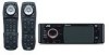
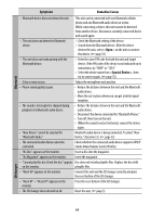
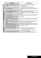
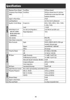
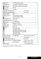
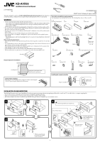
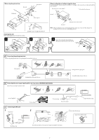
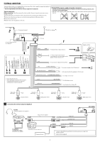
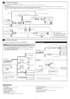
KD-AVX33 Installation/Connection Manual LVT1708-004A [A] This unit is designed to operate on 12 V DC, NEGATIVE ground electrical systems. If your vehicle does not have this system, a voltage inverter is required, which can be purchased at JVC car audio dealers. WARNINGS • DO NOT install any unit and wire any cable in locations where; - it may obstruct the steering wheel and gearshift lever operations, as this may result in a traffic accident. - it may obstruct the operation of safety devices such as air bags, as this may result in a fatal accident. - it may obstruct visibility. • DO NOT operate any unit while manipulating the steering wheel, as this may result in a traffic accident. • The driver must not watch the monitor while driving. If the driver watches the monitor while driving, it may lead to carelessness and cause an accident. • The driver must not put on the headphones while driving. It is dangerous to shut off the outside sounds while driving. • If you need to operate the unit while driving, be sure to look around carefully. • If the parking brake is not engaged, "Parking Brake" appears on the monitor, and no playback picture will be shown. - This warning appears only when the parking brake lead is connected to the parking brake system built in the car. Notes on electrical connections: • Replace the fuse with one of the specified rating. If the fuse blows frequently, consult your JVC car audio dealer. • It is recommended to connect to the speakers with maximum power of more than 50 W (both at the rear and at the front, with an impedance of 4 Ω to 8 Ω). If the maximum power is less than 50 W, change "Amplifier Gain" setting to prevent the speakers from being damaged (see page 51 of the INSTRUCTIONS). • To prevent short-circuit, cover the terminals of the UNUSED leads with insulating tape. • The heat sink becomes very hot after use. Be careful not to touch it when removing this unit. 0207MNMMDWJEIN EN ©2007 Victor Company of Japan, Limited Parts list for installation and connection The following parts are provided for this unit. After checking them, please set them correctly. A / B Hard case/Control panel C Sleeve D Trim plate E Power cord F Audio/video cord G H Crimp connectors Remote controller / Holder I Batteries J Double-sided adhesive tape K Microphone L Microphone clip M Reverse gear signal extension cord Heat sink Required space for installation Dashboard Control panel Trim plate is detached on this illustration for explanation. 5 mm 5 mm Caution when installing Fit the unit into the mounting sleeve by using four corners of the trim plate. • DO NOT press the panel (shaded in the illustration). N Washer (ø5) o Lock nut (M5) P Handles Q Rubber cushion R Mounting bolt- M5 x 20 mm Installing the remote controller Remote controller Holder Double-sided adhesive tape INSTALLATION (IN-DASH MOUNTING) The following illustration shows a typical installation. If you have any questions or require information regarding installation kits, consult your JVC car audio dealer or a company supplying kits. • If you are not sure how to install this unit correctly, have it installed by a qualified technician. • Make sure not to block the fan on the rear panel to maintain proper ventilation when installed. • You cannot install the unit on the car which has any obstacles in the space shown in "Required space for installation" above. Do the required electrical connections. Do not block the fan. Bend the appropriate tabs to hold the sleeve firmly in place. Fit the protrusions outside the unit. *1 When you stand the unit, be careful not to damage the fuse on the rear. 1
-
 1
1 -
2
-
3
-
4
-
5
-
6
-
7
-
8
-
9
-
10
-
11
-
12
-
13
-
14
-
15
-
16
-
17
-
18
-
19
-
20
-
21
-
22
-
23
-
24
-
25
-
26
-
27
-
28
-
29
-
30
-
31
-
32
-
33
-
34
-
35
-
36
-
37
-
38
-
39
-
40
-
41
-
42
-
43
-
44
-
45
-
46
-
47
-
48
-
49
-
50
-
51
-
52
-
53
-
54
-
55
-
56
-
57
-
58
-
59
-
60
-
61
-
62
-
63
-
64
-
65
-
66
-
67
-
68
-
69
-
70
-
71
-
72
-
73
-
74
-
75
-
76
-
77
-
78
-
79
-
80
-
81
-
82
-
83
-
84
-
85
-
86
-
87
-
88
-
89
-
90
-
91
-
92
-
93
-
94
-
95
-
96
-
97
-
98
-
99
-
100
-
101
-
102
-
103
-
104
-
105
-
106
-
107
-
108
-
109
-
110
-
111
-
112
-
113
-
114
-
115
-
116
-
117
-
118
-
119
-
120
-
121
-
122
-
123
-
124
-
125
-
126
-
127
-
128
-
129
-
130
-
131
-
132
-
133
-
134
-
135
-
136
-
137
-
138
-
139
-
140
-
141
-
142
-
143
-
144
-
145
-
146
-
147
-
148
-
149
-
150
-
151
-
152
-
153
-
154
-
155
-
156
-
157
-
158
-
159
-
160
-
161
-
162
-
163
-
164
-
165
-
166
-
167
-
168
-
169
-
170
-
171
-
172
-
173
-
174
-
175
-
176
-
177
-
178
-
179
-
180
-
181
-
182
-
183
-
184
-
185
-
186
-
187
-
188
-
189
-
190
-
191
-
192
-
193
-
194
-
195
-
196
-
197
-
198
-
199
-
200
-
201
-
202
-
203
-
204
-
205
-
206
-
207
-
208
-
209
-
210
-
211
-
212
-
213
-
214
-
215
-
216
-
217
-
218
-
219
-
220
-
221
-
222
-
223
-
224
-
225
-
226
-
227
-
228
-
229
-
230
-
231
-
232
-
233
-
234
-
235
-
236
-
237
-
238
-
239
-
240
-
241
-
242
-
243
-
244
-
245
-
246
-
247
-
248
-
249
-
250
-
251
-
252
-
253
-
254
-
255
-
256
-
257
-
258
-
259
-
260
-
261
-
262
-
263
-
264
-
265
-
266
-
267
-
268
-
269
-
270
-
271
-
272
-
273
-
274
-
275
-
276
-
277
-
278
-
279
-
280
-
281
-
282
-
283
-
284
-
285
-
286
-
287
-
288
-
289
-
290
-
291
-
292
-
293
-
294
-
295
-
296
-
297
-
298
-
299
-
300
-
301
-
302
-
303
-
304
-
305
-
306
-
307
-
308
-
309
-
310
-
311
-
312
-
313
-
314
-
315
-
316
-
317
-
318
-
319
-
320
-
321
-
322
-
323
-
324
-
325
-
326
-
327
-
328
-
329
-
330
-
331
-
332
-
333
-
334
-
335
-
336
-
337
-
338
-
339
-
340
-
341
-
342
-
343
-
344
-
345
-
346
-
347
-
348
-
349
-
350
-
351
-
352
-
353
-
354
-
355
-
356
-
357
-
358
-
359
-
360
-
361
-
362
-
363
-
364
-
365
-
366
-
367
-
368
-
369
-
370
-
371
-
372
-
373
-
 374
374 -
 375
375 -
 376
376 -
 377
377 -
 378
378 -
 379
379 -
 380
380 -
 381
381 -
 382
382
 |
 |