JVC KD-ADV38 Instructions - Page 381
Typical connections, PRECAUTIONS on power supply and speaker connections - audio harness
 |
UPC - 046838030499
View all JVC KD-ADV38 manuals
Add to My Manuals
Save this manual to your list of manuals |
Page 381 highlights
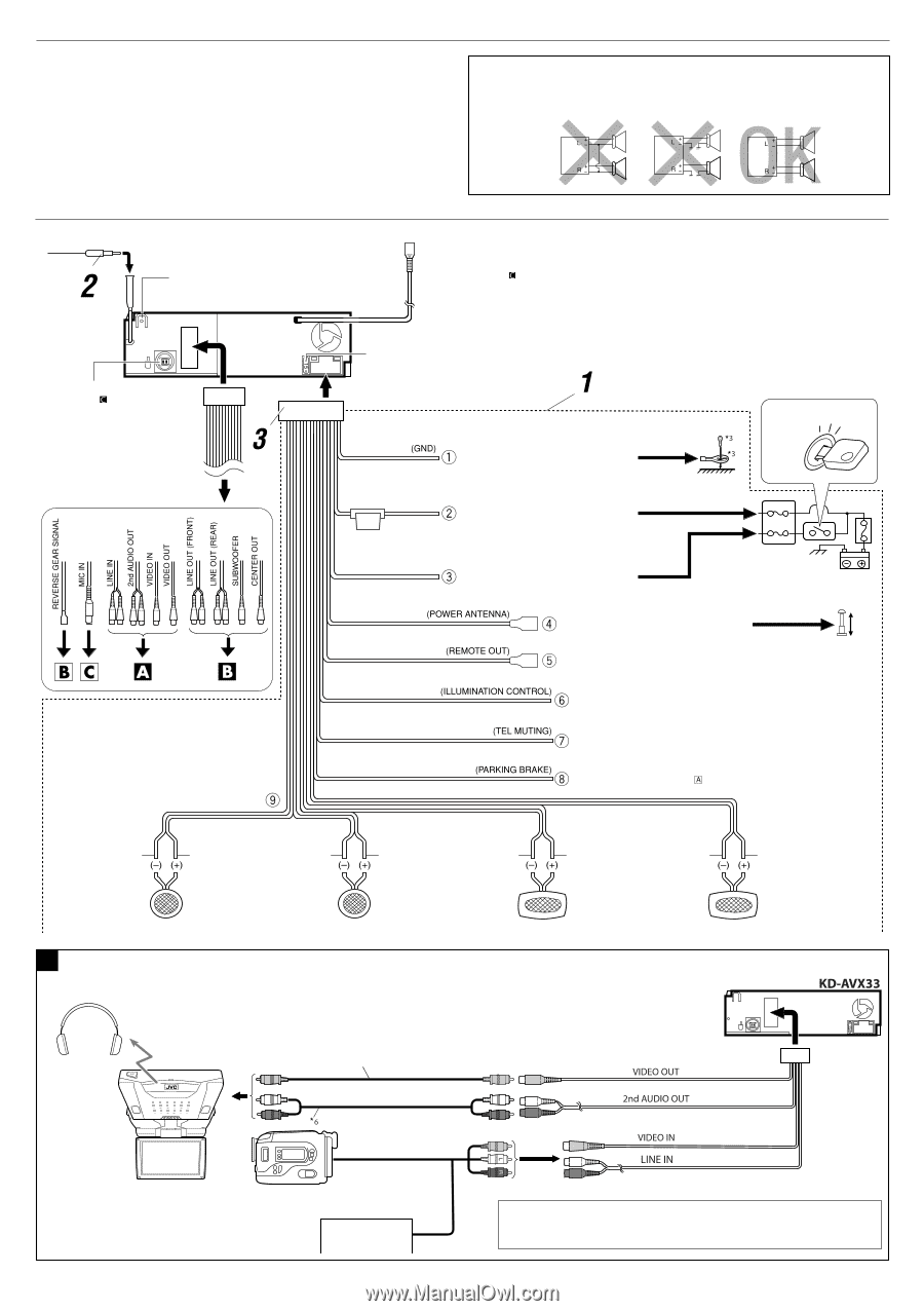
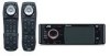
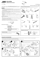
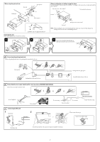
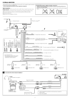
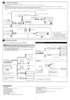
ELECTRICAL CONNECTIONS To prevent short circuits, we recommend that you disconnect the battery's negative terminal and make all electrical connections before installing the unit. • Be sure to ground this unit to the car's chassis again after installation. Typical connections Before connecting: Check the wiring in the vehicle carefully. Incorrect connection may cause serious damage to this unit. The leads of the power cord and those of the connector from the car body may be different in color. 1 Connect the colored leads of the power cord in the order specified in the illustration below. 2 Connect the antenna cord. 3 Finally connect the wiring harness to the unit. PRECAUTIONS on power supply and speaker connections: • DO NOT connect the speaker leads of the power cord to the car battery; otherwise, the unit will be seriously damaged. • BEFORE connecting the speaker leads of the power cord to the speakers, check the speaker wiring in your car. Rear ground terminal USB cable (see diagram ) To an external component (see diagram ) *3 Not included for this unit *4 Before checking the operation of this unit prior to installation, this lead must be connected, otherwise power cannot be turned on. 15 A fuse Black Yellow *4 Red Blue Blue with white stripe Orange with white stripe Brown Light green To metallic body or chassis of the car Ignition switch To a live terminal in the fuse block connecting to the car battery (bypassing the ignition switch) (constant 12 V) To an accessory terminal in the fuse block Fuse block To automatic antenna if any (250 mA max.) To the remote lead of other equipment (200 mA max.) To car light control switch To cellular phone system To parking brake (see diagram ) White with black stripe White Gray with black stripe Left speaker (front) Gray Green with black stripe Right speaker (front) A Connections for external component playback KS-HP2 Cordless headphones (not supplied) *5 Video cord (not supplied) Green Purple with black stripe Left speaker (rear) Purple Right speaker (rear) KV-MR9010 9-INCH WIDESCREEN MONITOR (not supplied) Camcorder, rear view camera, etc. Navigation System *5 To listen to disc playback sound while in Dual Zone operations (see page 26 of INSTRUCTIONS). *6 Audio cord (not supplied) 3
-
 1
1 -
2
-
3
-
4
-
5
-
6
-
7
-
8
-
9
-
10
-
11
-
12
-
13
-
14
-
15
-
16
-
17
-
18
-
19
-
20
-
21
-
22
-
23
-
24
-
25
-
26
-
27
-
28
-
29
-
30
-
31
-
32
-
33
-
34
-
35
-
36
-
37
-
38
-
39
-
40
-
41
-
42
-
43
-
44
-
45
-
46
-
47
-
48
-
49
-
50
-
51
-
52
-
53
-
54
-
55
-
56
-
57
-
58
-
59
-
60
-
61
-
62
-
63
-
64
-
65
-
66
-
67
-
68
-
69
-
70
-
71
-
72
-
73
-
74
-
75
-
76
-
77
-
78
-
79
-
80
-
81
-
82
-
83
-
84
-
85
-
86
-
87
-
88
-
89
-
90
-
91
-
92
-
93
-
94
-
95
-
96
-
97
-
98
-
99
-
100
-
101
-
102
-
103
-
104
-
105
-
106
-
107
-
108
-
109
-
110
-
111
-
112
-
113
-
114
-
115
-
116
-
117
-
118
-
119
-
120
-
121
-
122
-
123
-
124
-
125
-
126
-
127
-
128
-
129
-
130
-
131
-
132
-
133
-
134
-
135
-
136
-
137
-
138
-
139
-
140
-
141
-
142
-
143
-
144
-
145
-
146
-
147
-
148
-
149
-
150
-
151
-
152
-
153
-
154
-
155
-
156
-
157
-
158
-
159
-
160
-
161
-
162
-
163
-
164
-
165
-
166
-
167
-
168
-
169
-
170
-
171
-
172
-
173
-
174
-
175
-
176
-
177
-
178
-
179
-
180
-
181
-
182
-
183
-
184
-
185
-
186
-
187
-
188
-
189
-
190
-
191
-
192
-
193
-
194
-
195
-
196
-
197
-
198
-
199
-
200
-
201
-
202
-
203
-
204
-
205
-
206
-
207
-
208
-
209
-
210
-
211
-
212
-
213
-
214
-
215
-
216
-
217
-
218
-
219
-
220
-
221
-
222
-
223
-
224
-
225
-
226
-
227
-
228
-
229
-
230
-
231
-
232
-
233
-
234
-
235
-
236
-
237
-
238
-
239
-
240
-
241
-
242
-
243
-
244
-
245
-
246
-
247
-
248
-
249
-
250
-
251
-
252
-
253
-
254
-
255
-
256
-
257
-
258
-
259
-
260
-
261
-
262
-
263
-
264
-
265
-
266
-
267
-
268
-
269
-
270
-
271
-
272
-
273
-
274
-
275
-
276
-
277
-
278
-
279
-
280
-
281
-
282
-
283
-
284
-
285
-
286
-
287
-
288
-
289
-
290
-
291
-
292
-
293
-
294
-
295
-
296
-
297
-
298
-
299
-
300
-
301
-
302
-
303
-
304
-
305
-
306
-
307
-
308
-
309
-
310
-
311
-
312
-
313
-
314
-
315
-
316
-
317
-
318
-
319
-
320
-
321
-
322
-
323
-
324
-
325
-
326
-
327
-
328
-
329
-
330
-
331
-
332
-
333
-
334
-
335
-
336
-
337
-
338
-
339
-
340
-
341
-
342
-
343
-
344
-
345
-
346
-
347
-
348
-
349
-
350
-
351
-
352
-
353
-
354
-
355
-
356
-
357
-
358
-
359
-
360
-
361
-
362
-
363
-
364
-
365
-
366
-
367
-
368
-
369
-
370
-
371
-
372
-
373
-
374
-
375
-
 376
376 -
 377
377 -
 378
378 -
 379
379 -
 380
380 -
 381
381 -
 382
382
 |
 |