LG ARUB115BT2 Installation Manual
LG ARUB115BT2 Manual
 |
View all LG ARUB115BT2 manuals
Add to My Manuals
Save this manual to your list of manuals |
LG ARUB115BT2 manual content summary:
- LG ARUB115BT2 | Installation Manual - Page 1
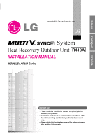
ÇAIS ESPAÑOL website http://www.lgservice.com LG System Heat Recovery Outdoor Unit R410A INSTALLATION MANUAL MODELS: ARUB Series IMPORTANT • Please read this installation manual completely before installing the product. • Installation work must be performed in accordance with the national wiring - LG ARUB115BT2 | Installation Manual - Page 2
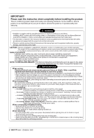
instructions in this manual can result in equipment malfunction, property damage, personal injury and/or death. CAUTION: Improper installation, adjustment, alteration, service or metal frame to provide added support. ... in a room: Properly vents. When connecting refrigerant tubing • Keep all - LG ARUB115BT2 | Installation Manual - Page 3
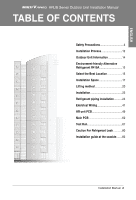
15 Select the Best Location 15 Installation Space 17 Lifting method 20 Installation 22 Refrigerant piping installation...........24 Electrical Wiring 41 HR unit PCB 49 Main PCB 60 Test Run 67 Caution For Refrigerant Leak 80 Installation guide at the seaside........82 Installation Manual 3 - LG ARUB115BT2 | Installation Manual - Page 4
all electric work done by a licensed electrician according to "Electric Facility Engineering Standard" and "Interior Wire Regulations" and the instructions given in this manual and always use a special circuit. • If the power source capacity is inadequate or electric work is performed improperly - LG ARUB115BT2 | Installation Manual - Page 5
the installed product, always contact a dealer or an Authorized Service Center. • There is risk of fire, electric shock, different refrigerant from the refrigerant specified on the unit. • If a different refrigerant or air is mixed with the original refrigerant, the refrigerant cycle Manual 5 - LG ARUB115BT2 | Installation Manual - Page 6
room could result. Don't use the existing manifold gage for R22 refrigerant. • Use the manifold gage for high pressure (R410A) as possible as for stable refrigerant filling. Don't mix and use the R22 pipe and the installation appliances that were used until now • Mixing the oil of R22 and R410A - LG ARUB115BT2 | Installation Manual - Page 7
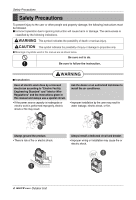
, explosion, or injury. Safety Precautions Use a dedicated outlet for this appliance. • There is risk of fire or electrical shock. Be cautious that . When the product is soaked (flooded or submerged), contact an Authorized Service Center. • There is risk of fire or electric shock. Be cautious - LG ARUB115BT2 | Installation Manual - Page 8
) leakage after installation or repair of product. • Low refrigerant levels may cause failure of product. Do not install the product where the noise or hot air from the outdoor unit could damage the neighborhoods. • It may cause a problem for your neighbors. Keep level even when installing the - LG ARUB115BT2 | Installation Manual - Page 9
. can significantly reduce the performance of the air conditioner or damage its parts. Do not block the inlet or outlet. • It may cause failure of appliance or accident. Installation Manual 9 - LG ARUB115BT2 | Installation Manual - Page 10
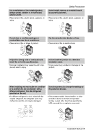
to ensure that water is drained away properly based on the installation manual. • A bad connection may cause water leakage. Be very careful , suspending it at the specified posi- tions on the unit base. Also support the outdoor unit at four points so that it cannot slip sideways. Safely dispose - LG ARUB115BT2 | Installation Manual - Page 11
ENGLISH Do not touch any of the refrigerant piping during and after operation. • off the main power switch. Otherwise it may result in water leakage or other problems. Auto-addressing should be done in condition of connecting the power of all indoor business due to noise. Installation Manual 11 - LG ARUB115BT2 | Installation Manual - Page 12
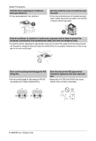
Avoid short circuits and ensure sufficient space is allowed for service Duct work Make sure airflow is sufficient Heat insulation work . Additional charge of refrigerant Recharge correctly as calculated in this manual and record the amount of added refrigerant Automatic addressing for Indoor - LG ARUB115BT2 | Installation Manual - Page 13
.6 inch of space between outdoor unit and the windbreak for easy air flow. 3) Select a well-drained place. 1. If you can't meet above guide line in the seaside installation, please contact LG Electronics for the additional anticorrosion treatment. 2. Periodic ( more than once/year ) cleaning of the - LG ARUB115BT2 | Installation Manual - Page 14
Model(HP(Ton)) 18(14.5) 20(16.0) 22(17.5) 24(19.0) Model ARUB173BT2 ARUB192BT2 ARUB211BT2 ARUB230BT2 ARUB096BT2 ARUB096BT2 ARUB115BT2 ARUB115BT2 ARUB076BT2 ARUB096BT2 ARUB096BT2 ARUB115BT2 Product Charge kg(lbs) 8+8(17.6+17.6) 8+8(17.6+17.6) 8+8(17.6+17.6) 8+8(17.6+17.6) CF(Correction - LG ARUB115BT2 | Installation Manual - Page 15
the developed countries have approved it as the environment-friendly refrigerant and encouraged to use it widely to prevent environment pollution flows out of unit when heating • With space for air passage and service work shown next • Because of the possibility of fire, do not Installation Manual 15 - LG ARUB115BT2 | Installation Manual - Page 16
HR unit suitable for following conditions • Avoid a place where rain may enter since the HR unit is for indoor. • Sufficient service space must be obtained. • Refrigerant pipe must not exceed limited length. • Avoid a place subject to a strong radiation heat from other heat source. • Avoid a place - LG ARUB115BT2 | Installation Manual - Page 17
A space of at least 250mm(9-13/16 inch) is necessary at the back for inlet air. Taking servicing, etc. from the rear into account, a space of about 915mm(36 inches) should be provided, B < Top view > A h H < Side view > B Rear Side A B Front Side < Top view > Front Side Installation Manual 17 - LG ARUB115BT2 | Installation Manual - Page 18
an obstruction above the unit A A A 45° or more B 200mm(7-7/8 inch) or more B B C 250mm(9-13/16 inch) or more C C < Front view > D Air guide E Air outlet guide (Procured at the site) D F 250mm(9-13/16 inch) or more E F < Side view > 390(15-3/8) 372.5(14-11/16) C < Front view > 587 - LG ARUB115BT2 | Installation Manual - Page 19
Rear Side Front Side Rear Side Front Side Rear Side D Front Side Rear Side D Front Side Rear Side D Front Side Rear Side Front Side Installation Manual 19 - LG ARUB115BT2 | Installation Manual - Page 20
Installation Space Seasonal wind and cautions in winter • Sufficient measures are required in a snow area or severe cold area in winter so that product can be operated well. • Get ready for seasonal wind or snow in winter even in other areas. • Install a suction and discharge duct not to let in snow - LG ARUB115BT2 | Installation Manual - Page 21
it. Otherwise plastic packaging bag may suffocate children to death. • When carrying in Outdoor Unit, be sure to support it at four points. Carrying in and lifting with 3-point support may make Outdoor Unit unstable, resulting in a fall. • Be very careful while carrying ARUN076DT2. It will be tilted - LG ARUB115BT2 | Installation Manual - Page 22
Installation Installation Location of anchor bolt(To be applied to 1, 2 Units installation) I Individual installation 10(3/8) Unit: mm(inch) UW1 UW1 700±2(27-9/16±1/16) 900±2 383 900±2 (35-7/16±1/16) (15-1/16) (35-7/16±1/16) I Collective installation 700±2 (27-9/16±1/16) UW1 UW1 UW1 - LG ARUB115BT2 | Installation Manual - Page 23
H-beam support as a base support • mounted. Otherwise, the support for installation may be pad between outdoor unit and base support to ensure that anti-vibration may surface) F H-Beam support G Concrete base support WARNING • Be sure for support strength when making a base support. • Don't use - LG ARUB115BT2 | Installation Manual - Page 24
: 25Nm (250kg-cm) or more). (Don't remove the internal part of the port) Service port: Make the refrigerant pipe vacuum and charge it using the service port. Always reattach caps after completing work (tightening torque of service cap: 10 lbf•ft or more). Liquid pipe Ball Valve(Liquid Pipe) Gas - LG ARUB115BT2 | Installation Manual - Page 25
outdoor unit, remove part and part . When connecting the pipes from the side of the outdoor unit, remove part (the whole "Knock out" part). Refrigerant piping installation (Front) WARNING After installing the pipe, clog the pipe excavation inlet of the front panel and the side panel (Wire may be - LG ARUB115BT2 | Installation Manual - Page 26
Refrigerant piping installation Connection of Outdoor Units 2 outdoor units Model Low Pressure Gas Pipe Liquid Pipe [Unit:mm(inch)] High Pressure Gas Pipe Ø34.9(1-3/8) Ø31.8(1-1/4) ARCNB20 Ø - LG ARUB115BT2 | Installation Manual - Page 27
into liquid pipe, low pressure gas pipe and high pressure gas pipe depending on status of refrigerant passing through the pipe. You must connect 3 pipes from outdoor unit to HR unit. For 3 indoor units : No. 1, 2, 3 (O), No. 1, 2, 4 (X), No.1, 3, 4 (X), No.2, 3, 4 (X). Installation Manual 27 - LG ARUB115BT2 | Installation Manual - Page 28
Refrigerant piping installation Type of HR Unit Select an HR unit according to the number of the indoor units to be installed. HR units are classified - LG ARUB115BT2 | Installation Manual - Page 29
ENGLISH [ Reducers for indoor unit and HR unit ] Refrigerant piping installation Models Liquid pipe [Unit:mm(inch)] Gas pipe High pressure Low pressure OD22.2(7/8) Ø19.05(3/4) OD28.58(1-1/8) Ø22.2(7/8) Ø19.25(3/4) OD15.88(5/8) Ø12.7(1/2) OD19.05(3/4) Ø15.88(5/8) Installation Manual 29 - LG ARUB115BT2 | Installation Manual - Page 30
properly. Insufficient insulation will result in a decline in heating/cooling performance, drip of condensate and other such problems. 11. When connecting the refrigerant piping, make sure the service valves of the outdoor unit is completely closed (the factory setting) and do not operate it until - LG ARUB115BT2 | Installation Manual - Page 31
site, be sure to make recharge refrigerant after perfect evacuation. - If a different refrigerant or air is mixed with the original refrigerant, the refrigerant cycle may malfunction and the unit between outdoor units) Unit: mm(inch) 1,280(50-3/8) Distance between outdoor units Installation Manual 31 - LG ARUB115BT2 | Installation Manual - Page 32
piping installation Refrigerant piping system Example : 3 outdoor units, 4 HR units and 11 indoor units Outdoor unit Y branch HR unit Indoor unit Slave 1 A2 Master A1 H h F2 E F1 E2 - LG ARUB115BT2 | Installation Manual - Page 33
ENGLISH Refrigerant piping installation ➲ Refrigerant pipe diameter between branches and HR units (B,C,D) Downward indoor unit total capacity [kW(Btu/h)] ≤ 5.6 (19,100) < 16.0 (54,600) < 22.4 ( 36k Gas pipe Liquid pipe 1234 12k 24k 24k 12k Indoor Unit 5678 48k 48k 48k 12k Installation Manual 33 - LG ARUB115BT2 | Installation Manual - Page 34
piping installation N Outdoor Unit Connection ➲ Refrigerant pipe diameter before 1st branch (A,E,F) Upward outdoor unit total capacity [HP] 8 10 12 14, 16 18, 20 22, 24 Liquid pipe [mm(inch)] Ø9.52(3/8) Ø9.52(3/8) Ø - LG ARUB115BT2 | Installation Manual - Page 35
Correction factor) Total amount(kg(lbs)) = A + B CAUTION If a negative result is obtained from the calculation, no refrigerant needs to be added. Ex) 10HP Outdoor unit HR unit (1EA) Indoor unit A: Ø12.7(1/2), 50m(164ft) B: of correction factor differs depending on model. Installation Manual 35 - LG ARUB115BT2 | Installation Manual - Page 36
from point A in direction of arrow Within ± 3° Within ± 3° • There is no limitation on the joint mounting configuration. • If the diameter of the refrigerant piping selected by the procedures described is different from the size of the joint, the connecting section should be cut with a pipe cutter - LG ARUB115BT2 | Installation Manual - Page 37
ENGLISH N Y branch pipe Refrigerant piping installation Models Low Pressure Gas Pipe Liquid pipe [Unit:mm(inch)] 12.7(1/2) O.D. 25.4(1) I.D. 15.88(5/8) O.D. 9.52(3/8) I.D. 6.35(1/4) O.D. 28.58(1-1/8) O.D. 19.05(3/4) I.D. 9.52(3/8) I.D. 22.2(7/8) I.D. 12.7(1/2) Installation Manual 37 - LG ARUB115BT2 | Installation Manual - Page 38
reduced after leaving for about one day after completion of nitrogen gas pressurization. * When charging of refrigerant is needed due to a defect of outdoor unit, pressurize after opening the service valves. During this test, please using the Vacuum Mode. High pressure gas pipe Liquid pipe Note - LG ARUB115BT2 | Installation Manual - Page 39
pipe is vacuumed via the HR unit). • If other refrigerants are mixed in the original refrigerant, a refrigerant cycle may cause malfunction or damage. • Add accurate refrigerant quantity via calculation. Too much or too little refrigerant may cause problems • Repeated on and off of the indoor units - LG ARUB115BT2 | Installation Manual - Page 40
piping Be sure to give insulation work to refrigerant piping by covering liquid pipe and gas pipe separately with enough thickness heat-resistant polyethylene, so that no gap is observed in the joint between - LG ARUB115BT2 | Installation Manual - Page 41
work using special circuits in accordance with regulations and this installation manual. If power supply circuit has a lack of capacity or and Outdoor Units, because the box is sometimes removed at the time of service work. 5. Never connect the main power source to terminal block of transmission - LG ARUB115BT2 | Installation Manual - Page 42
Electrical Wiring Outdoor Unit Indoor Unit Indoor Unit Remote controller Remote controller Outdoor Unit Indoor Unit Indoor Unit Remote controller Remote controller 2-Core Shield Cable Outdoor Unit Indoor Unit Indoor Unit Remote controller Remote controller Outdoor Unit Indoor Unit - LG ARUB115BT2 | Installation Manual - Page 43
(208/230V) Inverter PCB Inverter FAN PCB Noise Filter Main PCB Magnet switch Take care of the phase sequence of 3-phase 3-wire power system Installation Manual 43 - LG ARUB115BT2 | Installation Manual - Page 44
Electrical Wiring Communication and Power Lines 1) Communication cable • Types : shielding wire CVVS or CPEVS • Use wires of size : over 1.25mm2 • Insulation material : PVC • Maximum allowable temperature: 140°F • Maximum allowable line length: under 300m(984ft) 2) Remote control cable • Types : 3- - LG ARUB115BT2 | Installation Manual - Page 45
requirements should adhere to the wiring regulations of the region. 5. Power supply cords of parts of appliances for outdoor use should not be lighter than polychloroprene sheathed flexible cord. 6. Don't install an too large capacity may cause a malfunction of unit or fire. Installation Manual 45 - LG ARUB115BT2 | Installation Manual - Page 46
Use round pressure terminals for connections to the power terminal block. Round pressure terminal Power wire When none are available, follow the instructions below. • Do not connect wiring of different thicknesses to the power terminal block. (Slack in the power wiring may cause abnormal heat - LG ARUB115BT2 | Installation Manual - Page 47
INTERNET DRY1 DRY2 GND 12V BA BA Master Outdoor unit HR unit 3(A) 4(B) 3(A) 4(B) 3(A) 4(B) The GND terminal is a '-' terminal for the central controller, not ground line Installation Manual 47 - LG ARUB115BT2 | Installation Manual - Page 48
Electrical Wiring N Example Connection of Transmission Cable 2 Outdoor Units I When the power source is supplied to Each outdoor unit individually. 3 Phase 3 Wires Power supply (Main Switch) Power supply 1 Phase 60Hz 208/230V Power supply switch (Switch fuse : ELCB) Power supply switch (Switch - LG ARUB115BT2 | Installation Manual - Page 49
SW02M (Dip switch for setup of the function of HR unit) SW03M SW04M SW05M (Switch for addressing HR unit) SW01M SW01M/SW03M/SW04M (Switch for manual valve addressing) Switch for setup of HR Unit 1. Main function of SW02M SW02M ON S/W No.1 No.2 No.3 No.4 No.5 No.6 No.7 No.8 Selection Method for - LG ARUB115BT2 | Installation Manual - Page 50
HR Unit PCB 2) Selection of the model of the HR unit 2 1 123 1234 Initial Setting (For 2 rooms) PRHR020A (For 3 rooms) PRHR030A (For 4 rooms) PRHR040A 1 room Connected 2 rooms Connected 3 rooms Connected 4 rooms Connected ❈ Each model is shipped with the switches No.2 and No.3 pre- - LG ARUB115BT2 | Installation Manual - Page 51
.05(3/4) I.D. 22.2(7/8) I.D. 15.88(5/8) I.D. 9.52(3/8) I.D. 12.7(1/2) ARBLB03320 I.D. 15.88(5/8) I.D. 9.52(3/8) I.D. 6.35(1/4) I.D. 15.88(5/8) I.D. 12.7(1/2) I.D. 28.58(1-1/8) O.D. 22.2(7/8) I.D. 25.4(1)(1/1/8) I.D. 6.35(1/4) I.D. 9.52(3/8) I.D. 6.35(1/4) I.D. 9.52(3/8) Installation Manual 51 - LG ARUB115BT2 | Installation Manual - Page 52
increasing numbers starting from '0'. Ex) Installation of 3 HR units 34 1234 34 1234 34 1234 3. SW01M/SW03M/SW04M (Dip S/W and tact S/W for manual valve addressing) - Used in manual addressing of the valve in the HR unit - Set the address of the valve of the HR unit to the central control - LG ARUB115BT2 | Installation Manual - Page 53
HR Unit PCB Flow chart for auto addressing for indoor units and HR units 1) Auto addressing for indoor unit 2) Auto pipe detection 3) Manual pipe detection(Execute in case of Auto pipe detection failure) • Turn off all the indoor units before auto addressing. If indoor unit is operated, auto - LG ARUB115BT2 | Installation Manual - Page 54
Ex) HR ➠ The number of the indoor • Turn No.6 of SW03M of outdoor unit PCB off. • Reset the power of outdoor unit PCB, HR unit. • Manual pipe detection is completed WARNING • In case that central controller is not installed, remain the address data after installer sets central control address as he - LG ARUB115BT2 | Installation Manual - Page 55
one equal? Yes Completion of auto addressing Check power and communication wiring between outdoor, HR and indoor units Retry indoor unit auto-addressing after checking trouble Incompletion of auto addressing Installation Manual 55 - LG ARUB115BT2 | Installation Manual - Page 56
operation. NO Pipe detection error occur after 30 seconds. Check the installation of pipe of outdoor, indoor, HR unit Retry auto pipe detection after checking trouble Incompletion of auto pipe detection 56 Outdoor Unit - LG ARUB115BT2 | Installation Manual - Page 57
)HR ➠ The number of the indoor Enter the central control address into each indoor unit using its wired remote control. On the HR unit PCB, manually set address of each valve of the HR unit to the central control address of the indoor unit connected to the valve. Are the number - LG ARUB115BT2 | Installation Manual - Page 58
valve addressing (In case that an indoor unit of central control address "11" is connected to a valve #1 of an HR unit) • Prerequisite for manual valve addressing: central control address of each indoor unit must be preset differently at its wired remote control No. Display and setup Setup and - LG ARUB115BT2 | Installation Manual - Page 59
on. SW01M SW03M • Display: "11" is displayed in 7-SEG • Operation: Turn dip S/W No.1 on. 2 • 7-SEG disappeared SW01M SW03M Identification of Manual Valve ID (Address) No. Display and Setup Setup and Contents 1 • Operation: more than 2 dip switches turned on. SW01M SW03M • Display: "Er - LG ARUB115BT2 | Installation Manual - Page 60
Main PCB Main PCB SW01B SW02B (DIP S/W) (DIP S/W) 7 - Segment SW02V Auto addressing 60 Outdoor Unit - LG ARUB115BT2 | Installation Manual - Page 61
if the relevant DIP switch is not properly setup. Model Code Model Code 195 196 197 Unit (HP) 8 10 12 Unit Master Ref. R410A Installation Manual 61 - LG ARUB115BT2 | Installation Manual - Page 62
Main PCB I Setting the DIP switch (SW03M) • Set the dip switch with the power turned off. If you change the setting when the power is on, the changed setting is not applied immediately. The changed setting is applied at the moment that the power is on. • Instant indoor unit checking, data display - LG ARUB115BT2 | Installation Manual - Page 63
1234 5 67 1234 5 67 ON 1234 5 67 8 9 10 11 12 13 14 ON 1234 5 67 1234 5 67 1234 5 67 8 9 10 11 12 13 14 Installation Manual 63 ENGLISH - LG ARUB115BT2 | Installation Manual - Page 64
Main PCB 2. Settings of slave outdoor unit Function Slave SW01B Setting ON SW02B Setting ON 1234 5 67 1234 5 67 1234 5 67 8 9 10 11 12 13 14 3. Settings of corresponding outdoor unit Function Inv Back Up Unit Back Up SW01B Setting ON SW02B Setting ON 1234 5 67 1234 5 67 ON 1234 5 67 8 9 - LG ARUB115BT2 | Installation Manual - Page 65
) No. A group (A0~AF) No. B group (B0~BF) No. C group (C0~CF) No. D group (D0~DF) No. E group (E0~EF) No. F group (F0~FF) Installation Manual 65 - LG ARUB115BT2 | Installation Manual - Page 66
Main PCB WARNING • Valve address and central control address of its corresponding indoor unit should be set identical in manual addressing. EX) HR unit Valve (04) Valve (03) Valve (02) Valve (01) Indoor unit (04) Indoor unit (03) Indoor unit (02) Indoor unit (01) Central - LG ARUB115BT2 | Installation Manual - Page 67
ground may decrease to approx. 2 MΩ as a result of refrigerant accumulating in the internal compressor. If the insulation resistance is less opened NOTE: Be sure to tighten caps. 4 Check if there are any problems in automatic addressing or not: Check and confirm that there are no error Manual 67 - LG ARUB115BT2 | Installation Manual - Page 68
heat exchanger part Service necessary Low pressure error EEV clogged or discharge temperature error Service necessary When system fault occurs, the error code is displayed at indoor unit display or remote control display, the trouble shooting guide is in the service manual 68 Outdoor Unit - LG ARUB115BT2 | Installation Manual - Page 69
black button for 2 sec. on main PCB. Refrigerant Auto Charging Press the black button until '508' is displayed Refrigerant Checking Press the black button until '608' is sec. after turning off all of dip S/W. Completed. Refrigerant Auto Charging Refrigerant Checking Installation Manual 69 - LG ARUB115BT2 | Installation Manual - Page 70
Test Run Sensor Check Error Code Display In case error occurs during sensor checking process, error display is as shown below. Following contents are displayed one after the other on the main PCB of master outdoor unit. Indoor sensor error : 319 Outdoor sensor error : 309 Displaying error content - LG ARUB115BT2 | Installation Manual - Page 71
checking. Judging Refrigerant Amount Excess of Refrigerant Scarcity of Refrigerant IDU, ODU are turned off Impossible To Judge Note Main PCB Press the black button on main PCB SW01V Press the black button for 2 sec. after turning off all of dip S/W. Completed Note 1) Installation Manual 71 - LG ARUB115BT2 | Installation Manual - Page 72
total refrigerant, recharge the refrigerant by using Refrigerant Auto Charging Function. 3. Scarcity of Refrigerant(629) Charge the refrigerant by using Refrigerant Auto Charging Function. 4. Impossible to Judge(639) IF the system is not in order, check the other problem except refrigerant. 72 - LG ARUB115BT2 | Installation Manual - Page 73
510 5 12 4 4 times 1 time 450 8 9 5 5 times 1 time 450 6.5 10.5 6 6 times 1 time 450 5 12 7 7 times 1 time 400 8 9 8 8 times 1 time 400 6.5 10.5 9 9 times 1 time 400 5 12 Installation Manual 73 - LG ARUB115BT2 | Installation Manual - Page 74
Test Run Vacuum Mode This function is used for creating vacuum in the system after compressor replacement, ODU parts replacement or IDU addition/replacement. Main PCB SW01S Main PCB SW02B Main PCB SW01V Vacuum mode setting method ODU power reset Master main PCB DIP switch ON ( No.11,14) Press the - LG ARUB115BT2 | Installation Manual - Page 75
and 7-segment LED of outdoor unit control board as shown in the table. • If more than two troubles occur simultaneously, lower number of error code is first displayed. • After error occurrence, if error is System is turned off by slave outdoor unit high pressure switch. Installation Manual 75 - LG ARUB115BT2 | Installation Manual - Page 76
Test Run Outdoor unit related error Display Title Cause of Error 1 Master Outdoor Unit Input Voltage Master Outdoor Unit input voltage is over 487V or 25 High/ Low Voltage below 270V 2 slave Outdoor Unit Input Voltage slave Outdoor Unit input voltage is over 487V or below High/ Low Voltage - LG ARUB115BT2 | Installation Manual - Page 77
of R, S, T power of slave outdoor unit 5 9 1 Mixing Installation of Sub Outdoor Unit Mixing Installation of Old Sub outdoor unit and New Slave Outdoor Unit Installation Manual 77 - LG ARUB115BT2 | Installation Manual - Page 78
Test Run Outdoor unit related error Display Title 6 0 1 Inverter PCB EEPROM Error of Master Outdoor Unit 2 Inverter PCB EEPROM Error of slave Unit Cause of Error Access Error of Inverter PCB of Master Outdoor Unit Access Error of Inverter PCB of slave Outdoor Unit 1 Master Outdoor Unit - LG ARUB115BT2 | Installation Manual - Page 79
Master Outdoor Unit Fan PCB Heat Sink Temperature Sensor open or short slave Outdoor Unit Fan PCB Heat Sink Temperature Sensor open or short Installation Manual 79 - LG ARUB115BT2 | Installation Manual - Page 80
room. I Limiting concentration Limiting concentration is the limit of Freon gas concentration where immediate measures can be taken without hurting human body when refrigerant leaks in the air. The limiting concentration shall be described in the unit of lb/ft3 (Freon gas weight per unit air volume - LG ARUB115BT2 | Installation Manual - Page 81
unit I Calculate refrigerant concentration Total amount of replenished refrigerant in refrigerant facility (lb) indoor unit is installed (ft3) = Refrigerant concentration (lb/ft 3) (R410A) In with mechanical ventilator. Reducing the outdoor refrigerant qty. Countermeasure 2 Gas leak alarm - LG ARUB115BT2 | Installation Manual - Page 82
.6 inch of space between outdoor unit and the windbreak for easy air flow. 3) Select a well-drained place. 1. If you can't meet above guide line in the seaside installation, please contact LG Electronics for the additional anticorrosion treatment. 2. Periodic ( more than once/year ) cleaning of the - LG ARUB115BT2 | Installation Manual - Page 83
P/No.: MFL46912304 Printed in Korea After reading this manual, keep it in a place easily accessible to the user for future reference.
-
 1
1 -
 2
2 -
 3
3 -
 4
4 -
 5
5 -
 6
6 -
 7
7 -
8
-
9
-
10
-
11
-
12
-
13
-
14
-
15
-
16
-
17
-
18
-
19
-
20
-
21
-
22
-
23
-
24
-
25
-
26
-
27
-
28
-
29
-
30
-
31
-
32
-
33
-
34
-
35
-
36
-
37
-
38
-
39
-
40
-
41
-
42
-
43
-
44
-
45
-
46
-
47
-
48
-
49
-
50
-
51
-
52
-
53
-
54
-
55
-
56
-
57
-
58
-
59
-
60
-
61
-
62
-
63
-
64
-
65
-
66
-
67
-
68
-
69
-
70
-
71
-
72
-
73
-
74
-
75
-
76
-
77
-
78
-
79
-
80
-
81
-
82
-
83
 |
 |
System
Heat Recovery Outdoor Unit
INSTALLATION MANUAL
LG
MODELS: ARUB Series
website http://www.lgservice.com
IMPORTANT
• Please read this installation manual completely before
installing the product.
• Installation work must be performed in accordance with
the national wiring standards by authorized personnel
only.
• Please retain this installation manual for future reference
after reading it thoroughly.
R410A
ENGLISH
FRANÇAIS
ESPAÑOL