LG ARUB115BT2 Installation Manual - Page 27
Installation of Outdoor Unit, HR Unit, Indoor Unit Refrigerant Pipe, Installation procedure for HR
 |
View all LG ARUB115BT2 manuals
Add to My Manuals
Save this manual to your list of manuals |
Page 27 highlights
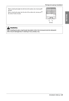
ENGLISH Refrigerant piping installation Installation procedure for HR unit 1. Using an insert-hole-in- anchor, hang the hanging bolt. 2. Install a hexagon nut and a flat washer (locally-procured)to the hanging bolt as shown in the figure in the bottom, and fit the main unit to hang on the hanger metal. Six-sided Nut 3. After checking with a level that the unit is level, tighten the hexagon nut. (M10 or M8) * The tilt of the unit should be within ±5° in front/back and left/right. Hanger metal 4. This unit should be installed suspended from ceiling and side A should always be facing up. 5. Insulate not used pipes completely as shown in the figure. Flat washer (M10) Hanging bolt (M10 or M8) A Insulation Installation of Outdoor Unit, HR Unit, Indoor Unit Refrigerant Pipe 3 pipes are connected to the HR unit from the outdoor unit, classified into liquid pipe, low pressure gas pipe and high pressure gas pipe depending on status of refrigerant passing through the pipe. You must connect 3 pipes from outdoor unit to HR unit. For connection between indoor unit and HR unit, you must connect both liquid pipe and gas pipe from the HR unit to the indoor unit. In this case, connect them to the indoor unit starting from No.1 connection port of the HR unit (the port number is displayed on ports of the HR unit). Use auxiliary flare as annexed parts in connection to the indoor unit. Low pressure Gas pipe HR Unit 1234 Liquid pipe High pressure Gas pipe Gas pipe Liquid pipe Gas pipe Liquid pipe CAUTION: Whenever connecting the indoor units with the HR unit, install the indoor units in numerical order from No.1. Ex) In case of installing 3 indoor units : No. 1, 2, 3 (O), No. 1, 2, 4 (X), No.1, 3, 4 (X), No.2, 3, 4 (X). Installation Manual 27
-
 1
1 -
2
-
3
-
4
-
5
-
6
-
7
-
8
-
9
-
10
-
11
-
12
-
13
-
14
-
15
-
16
-
17
-
18
-
19
-
20
-
21
-
 22
22 -
 23
23 -
 24
24 -
 25
25 -
 26
26 -
 27
27 -
 28
28 -
 29
29 -
 30
30 -
 31
31 -
 32
32 -
33
-
34
-
35
-
36
-
37
-
38
-
39
-
40
-
41
-
42
-
43
-
44
-
45
-
46
-
47
-
48
-
49
-
50
-
51
-
52
-
53
-
54
-
55
-
56
-
57
-
58
-
59
-
60
-
61
-
62
-
63
-
64
-
65
-
66
-
67
-
68
-
69
-
70
-
71
-
72
-
73
-
74
-
75
-
76
-
77
-
78
-
79
-
80
-
81
-
82
-
83
 |
 |
