LG ARUB115BT2 Installation Manual - Page 24
Refrigerant piping installation
 |
View all LG ARUB115BT2 manuals
Add to My Manuals
Save this manual to your list of manuals |
Page 24 highlights
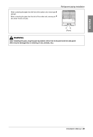
Refrigerant piping installation Refrigerant piping installation WARNING Always use extreme care to prevent the refrigerant gas (R410A) from leakage while using fire or flame. If the refrigerant gas comes in contact with the flame from any source, such as a gas stove, it breaks down and generates a poisonous gas which can cause gas poisoning. Never perform brazing in an unventilated room. Always conduct an inspection for gas leakage after installation of the refrigerant piping has been completed. Cautions in pipe connection/valve operation Cut both the pipe and the valve with a cutter to suit the length (Don't cut the length of less than 70mm(2.8inch)) Open status when both the pipe and the valve are in a straight line. CLOSE OPEN WARNING After completing work, securely tighten both service ports and caps so that gas does not leak. Pipe joint (auxiliary parts): Securely perform brazing with a nitrogen blow into the service valve port.(Releasing pressure : 0.29 psi or less) Flare nut: Loose or tighten flare nut by using the wrench with both ends. Coat the flare connection part with oil for the compressor. Cap: Remove caps and operate valve, etc. After operation, always reattach caps (tightening torque of valve cap: 25Nm (250kg-cm) or more). (Don't remove the internal part of the port) Service port: Make the refrigerant pipe vacuum and charge it using the service port. Always reattach caps after completing work (tightening torque of service cap: 10 lbf•ft or more). Liquid pipe Ball Valve(Liquid Pipe) Gas pipe Elbow joint (field supply) Elbow Ball Valve(Gas Pipe) 24 Outdoor Unit
-
 1
1 -
2
-
3
-
4
-
5
-
6
-
7
-
8
-
9
-
10
-
11
-
12
-
13
-
14
-
15
-
16
-
17
-
18
-
 19
19 -
 20
20 -
 21
21 -
 22
22 -
 23
23 -
 24
24 -
 25
25 -
 26
26 -
 27
27 -
 28
28 -
 29
29 -
30
-
31
-
32
-
33
-
34
-
35
-
36
-
37
-
38
-
39
-
40
-
41
-
42
-
43
-
44
-
45
-
46
-
47
-
48
-
49
-
50
-
51
-
52
-
53
-
54
-
55
-
56
-
57
-
58
-
59
-
60
-
61
-
62
-
63
-
64
-
65
-
66
-
67
-
68
-
69
-
70
-
71
-
72
-
73
-
74
-
75
-
76
-
77
-
78
-
79
-
80
-
81
-
82
-
83
 |
 |
