MSI MS 7030 User Guide - Page 32
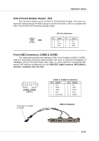
Front Panel Audio Connector: JAUD1, CD-In Connector: JCD1
 |
View all MSI MS 7030 manuals
Add to My Manuals
Save this manual to your list of manuals |
Page 32 highlights
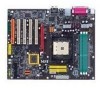
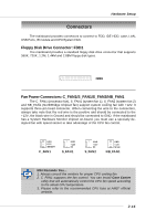
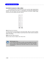
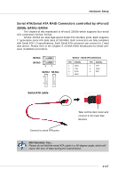
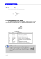
MS-7030 ATX Mainboard CD-In Connector: JCD1 The connector is for CD-ROM audio connector. L JCD1 GND R Front Panel Audio Connector: JAUD1 The JAUD1 front panel audio connector allows you to connect to the front panel audio and is compliant with Intel® Front Panel I/O Connectivity Design Guide. JAUD1 2 10 1 9 Pin Definition PIN SIGNAL DESCRIPTION 1 AUD_MIC Front panel microphone input signal 2 AUD_GND Ground used by analog audio circuits 3 AUD_MIC_BIAS Microphone power 4 AUD_VCC Filtered +5V used by analog audio circuits 5 AUD_FPOUT_R Right channel audio signal to front panel 6 AUD_RET_R Right channel audio signal return from front panel 7 HP_ON Reserved for future use to control headphone amplifier 8 KEY No pin 9 AUD_FPOUT_L Left channel audio signal to front panel 10 AUD_RET_L Left channel audio signal return from front panel MSI Reminds You... If you don't want to connect to the front audio header, pins 5 & 6, 9 & 10 have to be jumpered in order to have signal output directed to the rear audio ports. Otherwise, the Line-Out connector on the back panel will not function. 6 10 59 2-20
-
 1
1 -
2
-
3
-
4
-
5
-
6
-
7
-
8
-
9
-
10
-
11
-
12
-
13
-
14
-
15
-
16
-
17
-
18
-
19
-
20
-
21
-
22
-
23
-
24
-
25
-
26
-
 27
27 -
 28
28 -
 29
29 -
 30
30 -
 31
31 -
 32
32 -
 33
33 -
 34
34 -
 35
35 -
 36
36 -
 37
37 -
38
-
39
-
40
-
41
-
42
-
43
-
44
-
45
-
46
-
47
-
48
-
49
-
50
-
51
-
52
-
53
-
54
-
55
-
56
-
57
-
58
-
59
-
60
-
61
-
62
-
63
-
64
-
65
-
66
-
67
-
68
-
69
-
70
-
71
-
72
-
73
-
74
-
75
-
76
-
77
-
78
-
79
-
80
-
81
-
82
-
83
-
84
-
85
-
86
-
87
-
88
-
89
-
90
-
91
-
92
-
93
-
94
-
95
-
96
-
97
-
98
-
99
-
100
-
101
-
102
-
103
-
104
-
105
-
106
-
107
-
108
-
109
-
110
-
111
-
112
-
113
 |
 |