Mackie SR408 / SR568 Owner's Manual
Mackie SR408 / SR568 Manual
 |
View all Mackie SR408 / SR568 manuals
Add to My Manuals
Save this manual to your list of manuals |
Mackie SR408 / SR568 manual content summary:
- Mackie SR408 / SR568 | Owner's Manual - Page 1
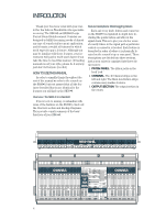
5 DIRECT OUT 4 DIRECT OUT 3 DIRECT OUT 2 DIRECT OUT 1 DIRECT OUT AUX SEND (BAL/UNBAL) "B" AUX RETURNS (BAL/UNBAL) MAIN AUX RETURNS ™ SR40•8/SR56•8 OWNER'S MANUAL 1 2 3 4 5 6 7 8 9 10 11 12 13 14 15 16 17 18 19 20 21 22 23 24 22 22 22 22 22 22 22 22 22 22 - Mackie SR408 / SR568 | Owner's Manual - Page 2
the user of the presence of important operating and maintenance (servicing) instructions in the literature accompanying the appliance. Le point d'exclamation not installed properly and used in accordance with the instruction manual, may cause harmful interference to radio communications. Operation - Mackie SR408 / SR568 | Owner's Manual - Page 3
new SR40•8. Or you might be one of those people who never read manuals. Either way, all we ask is that you read this page now write your serial numbers here for future reference (i.e., insurance claims, tech support, return authorization, etc.): Console Purchased at: Power Supply Date of purchase - Mackie SR408 / SR568 | Owner's Manual - Page 4
more. Although you may be familiar with these features, your investment will pay for itself much faster if you take the time to read this manual. (If reading manuals is not your style, please do it anyway, just don't tell anyone you did.) HOW TO USE THIS - Mackie SR408 / SR568 | Owner's Manual - Page 5
unbalanced" leave you blank, flip to the glossary at the back of this manual for a quick explanation. This icon marks information that is critically important or unique A Plug For The Connectors Section Also at the back of this manual is a section on connectors: XLR, TRS and RCA connectors, balanced - Mackie SR408 / SR568 | Owner's Manual - Page 6
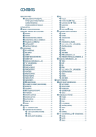
CONTENTS READ THIS PAGE 3 LEVEL-SETTING PROCEDURE 3 HYPER-QUICK-TURBO METHOD 3 ALTERNATE METHOD 3 OTHER NUGGETS OF WISDOM 3 INTRODUCTION 4 SR40•8 HOOKUP EXAMPLES 8 OVERVIEW: THE SR40•8 IN A NUTSHELL 10 MIXING 10 MATRIX 10 STAGE MONITORS & EFFECTS 10 MONITORING, SOLO & METERING 11 - Mackie SR408 / SR568 | Owner's Manual - Page 7
TABLE OF MIDI NOTE MESSAGES .... 54 SR40•8 BLOCK DIAGRAM 56 SR40•8 GAIN STRUCTURE DIAGRAM 58 SPECIFICATIONS 60 APPENDIX A: Service Info 62 TROUBLESHOOTING 62 APPENDIX B: Glossary 63 APPENDIX C: Connections 72 APPENDIX D: Balanced Lines, Phantom Powering, Grounding, and Other Arcane Mysteries - Mackie SR408 / SR568 | Owner's Manual - Page 8
SR40•8 HOOKUP EXAMPLES Stage Monitor Stage Monitor Stage Monitor Stage Monitor Power Amp Power Amp Power Amp Power Amp mono mode mono mode mono mode mono mode Power Amp mono mode PFL Monitor Reverb #1 Reverb #2 Delay Harmonizer Vocal Maximizer Stereo EQ and Compressor DAT Recorder SEND - Mackie SR408 / SR568 | Owner's Manual - Page 9
Stage Monitor Stage Monitor Power Amp mono mode Stage Monitor Power Amp mono mode Stage Monitor Power Amp mono mode Power Amp mono mode Vocal Compressor Reverb #1 Reverb #2 Delay Harmonizer Cassette Recorder DAT Recorder SEND SUB INSERTS (BAL/UNBAL) 1 RETURN SEND 5 RETURN MAIN INSERTS - Mackie SR408 / SR568 | Owner's Manual - Page 10
OVERVIEW: THE SR40•8 IN A NUTSHELL This section provides a quick summary of the SR40•8's major features. It is not intended to be a dissertation on how to use a mixer, especially the SR40•8, where the possibilities are endless. Just the same, it's a good place to get started. MIXING Channel - Mackie SR408 / SR568 | Owner's Manual - Page 11
MONITORING, SOLO, & METERING Usually an engineer listens to the left/right mix (with the center mix blended in), just as the audience is hearing it. Signals available for monitoring by the engineer are available via either of the high-powered headphone outputs, with level control, or a line-level - Mackie SR408 / SR568 | Owner's Manual - Page 12
PATCH PANEL At the risk of stating the obvious, this is where you plug everything in: microphones, instruments, effects, headphones, and the ultimate destination for your sound: PA system, tape recorder and the like. E-Z INTERFACE Concerned about levels, balancing, impedances, polarity, or other - Mackie SR408 / SR568 | Owner's Manual - Page 13
LINE IN Point Before: Balanced or unbalanced mic- or line-level cable with 1⁄4" TRS or TS connector, (tip = hot, ring = cold, sleeve = shield). Point After: Channel . This input is similar to the MIC input, but without phantom power. Both signals mix together at the mic preamp. Mic-level signals can - Mackie SR408 / SR568 | Owner's Manual - Page 14
MAIN AUX RETURNS (A1-A4) Point Before: Balanced or unbalanced linelevel cable with 1⁄4" TRS or TS connector, (tip = hot, ring = cold, sleeve = shield). Point After: MAIN AUX RETURNS (A1-A4) . The left jack's signal is normalled to the right jack - a mono signal, patched into the left jack only, - Mackie SR408 / SR568 | Owner's Manual - Page 15
TAPE INPUT Point Before: Unbalanced line-level cable with RCA connector. Point After: TAPE RETURNS . RCA jacks, bless their little hearts, have no normalling - if you need a mono signal to appear on both sides, that will require a Y-splitter so that both jacks can be patched. This is a good place to - Mackie SR408 / SR568 | Owner's Manual - Page 16
MAIN OUTPUTS Point Before: LEFT/RIGHT/CENTER mixes , MAIN INSERTS ,LEFT/RIGHT/CENTER Faders . Point After: Balanced or unbalanced cable with female XLR connector (pin 2 = hot, pin 3 = cold, pin 1 = shield). Unless you've created an elaborate main mix using the MATRIX , patch these outputs to - Mackie SR408 / SR568 | Owner's Manual - Page 17
SUB INSERTS Point Before: SUB 1-8 mixes , AIR , FLIP . Point After: SUBS 1-8 Faders . Both the SEND and RETURN jacks are balanced, but can accommodate unbalanced TS cables. Signal feeding the SEND jack is also sent to the RETURN jack's normalling pins. With nothing plugged into the RETURN jack, the - Mackie SR408 / SR568 | Owner's Manual - Page 18
MONITOR Point Before: INSERT (HEADPHONES) . Point After: Balanced or unbalanced cable with 1⁄4" TRS or TS connector. Patch these outputs to an amp's inputs, and patch the amp's outputs to speakers mounted at the console. Alternatively, the MONITOR outputs can deliver the FOH (front-of-house) - Mackie SR408 / SR568 | Owner's Manual - Page 19
INTERCOM Point Before: Externally supplied ClearCom™ or compatible party-line intercom line, with power. Point After: SR40•8 intercom interface, headphone amplifiers, and talkback system. This connector accepts a 3-pin male XLR connector connected to a Clear-Com or compatible party-line intercom - Mackie SR408 / SR568 | Owner's Manual - Page 20
) switch. Have you read the Level-Setting Procedure yet? If not, go to item right now and read it - it's at the beginning of this manual. That procedure is basically "How to Use the Trim Control." We ask that you commit that procedure to memory. You'll be glad you did - Mackie SR408 / SR568 | Owner's Manual - Page 21
: The HI-MID and LOW-MID frequencies can be set to the same frequencies as the HI and LOW shelving EQs. This is usually not a problem, but it is unnecessary by virtue of being redundant, and can sometimes cause clipping. For instance, if you fully boost the LOW-MID, with the - Mackie SR408 / SR568 | Owner's Manual - Page 22
U -15 +15 U -15 +15 2.5k EQ HI 12k HI MID 700 6k FREQ 500 15k U -15 +15 250 LOW MID 70 700 FREQ 45 3k U -15 +15 LOW 80Hz HPF 150 EQ IN 75 220 45 350 FREQ 30 800 LR PAN 40 MUTE dB 5 1-2 U 3-4 5-6 5 7-8 CENTER L-R 50 60 OO SOLO LOW MID and FREQ The LOW-MID EQ has a - Mackie SR408 / SR568 | Owner's Manual - Page 23
want much more definition. With HPF, you can safely boost LOW EQ and LOW-MID EQ. Many times bass shelving EQ can really benefit voices. Trouble is, adding LOW shelving EQalso boosts the infrasonic debris: stage rumble, mic handling clunks, wind noise, and breath pops. HPF removes all that debris so - Mackie SR408 / SR568 | Owner's Manual - Page 24
U -15 +15 U -15 +15 2.5k EQ HI 12k HI MID 700 6k FREQ 500 15k U -15 +15 250 LOW MID 70 700 FREQ 45 3k U -15 +15 LOW 80Hz HPF 150 EQ IN 75 220 45 350 FREQ 30 800 LR PAN 40 MUTE dB 5 1-2 U 3-4 5-6 5 7-8 CENTER L-R 50 60 OO SOLO FADER Point Before: MUTE . Point After: - Mackie SR408 / SR568 | Owner's Manual - Page 25
LEFT/RIGHT mix . If you want to create a Subgroup of certain Channels, engage one of the numbered switches instead of the L-R, and the signals from those Channels are sent to the appropriate Subgroup Fader . From there, the Subgroups can be sent back to the main LEFT/RIGHT mix , allowing you to use - Mackie SR408 / SR568 | Owner's Manual - Page 26
LINE MIC +48 PH TRIM 40 0 60 -20dB +40dB 0 GAIN U AUX 1 +15 U OO OO OO OO OO OO OO OO 2 +15 U 3 +15 U 4 +15 PRE U 5 +15 U 6 +15 U 7 +15 U 8 +15 PRE FDR POST EQ Be further aware: If this happens, remem- AUX SEND ber that you still have the Subgroup 1 SOLO switched engaged, even - Mackie SR408 / SR568 | Owner's Manual - Page 27
PRE FDR/POST EQ (AUX SENDS 5-8) Point Before: Fader (switch up), EQ IN (switch down). Point After: AUX sends 5-8 . This switch has one difference from the PRE switch for AUX sends 1-4: In the PRE mode (named POST EQ), the tap point is still before the Channel Fader, but after the EQ, instead of - Mackie SR408 / SR568 | Owner's Manual - Page 28
OO OO OO OO OO OO OO OO OO U AUX 1 +15 U 2 +15 U 3 +15 U 4 +15 A4 PRE U 5 +15 U 6 +15 U 7 +15 U 8 +15 PRE FDR POST EQ LR PAN A4 MUTE PAN Being that these are stereo Channels, their PAN controls are similar to a balance control on a home stereo - if you turn it to the right, you - Mackie SR408 / SR568 | Owner's Manual - Page 29
OUTPUT SECTION You've just learned about the Channels and MAIN AUX RETURNS (A1-A4), and how the signals get in and out. In the output section, things get a bit more complicated, so put on your thinking cap. LEFT/RIGHT/CENTER MIXES This is where everything assigned via the 1-2, 3-4, 5-6, 7-8, L-R, - Mackie SR408 / SR568 | Owner's Manual - Page 30
CENTER FADER Point Before: MAIN INSERTS . Point After: MAIN OUTPUTS . The CENTER mix is off with this Fader fully down, the "U" marking is unity gain, and fully up provides 10dB additional gain. Remember that the CENTER mix is not actually related to the LEFT and RIGHT mix (except that they usually - Mackie SR408 / SR568 | Owner's Manual - Page 31
Remember: INPUTS SOLO has precedence over OUTPUTS SOLO - you can't combine these signals. SUBS (SUB 1-8 MIXES) This is where everything assigned via the 1-2, 3-4, 5-6, and 7-8 Channel assignment switches gets mixed together. Just after the mix stage, the signals are sent out to the SUB INSERTS , - Mackie SR408 / SR568 | Owner's Manual - Page 32
OO 1 5 0 +10 AIR 16kHz ASSIGN CENTER L-R LR PAN 1 MUTE dB 10 5 U 5 10 20 30 40 50 60 SOLO a secondary feed, you'll want to use the MATRIX section. Use MATRIX A for the LEFT and MATRIX B for the RIGHT secondary mix outputs. Turn MATRIX A's LEFT knob and MATRIX B's RIGHT knob to their "U" markings. - Mackie SR408 / SR568 | Owner's Manual - Page 33
"B" AUX RETURNS AND TAPE RETURNS The four "B" AUX RETURNS and the two TAPE RETURNS are basically the same, but with different input hardware . They're your basic, no-frills, stereo Channels. AUX RETURNS B1, B2, B3, TAPE A and TAPE B are dedicated to the LEFT/RIGHT mix, and AUX RETURN B4 is dedicated - Mackie SR408 / SR568 | Owner's Manual - Page 34
AUX SEND MASTERS The AUX SEND MASTERS, as with all the signal paths in the SR40•8, are fully equipped with LEVEL, MUTE, and SOLO controls. Using the FLIP feature, AUX SEND MASTERS can be routed through the subgroups (SUB 1-8 mixes) circuitry instead, providing the engineer with more control over - Mackie SR408 / SR568 | Owner's Manual - Page 35
MUTE Point Before: LEVEL . Point After: AUX SEND . Muting removes the signal from its AUX SEND output and AFL SOLO. The PFL SOLO and PFL Meter paths are not affected. Pressing the switch toggles the electronic mute relay living in the signal path's circuitry. If the signal is muted, pressing the - Mackie SR408 / SR568 | Owner's Manual - Page 36
SOLO LEVEL Point Before: INPUTS PFL/AFL and OUTPUTS PFL/AFL switches. Point After: HEADPHONES and MONITOR . This controls the signal level of all SOLO signals, be they from the INPUTS, OUTPUTS, PFL, or AFL. The signal is off when turned fully counterclockwise, with 10dB gain turned fully - Mackie SR408 / SR568 | Owner's Manual - Page 37
MONITOR MONITOR signals are a line-level equivalent of the HEADPHONES output. The TRS MONITOR outputs are designed for special situations such as these: You can use these jacks to deliver the FOH (front-of-house) headphone mix to an engineer operating a secondary stage monitor console. If you want - Mackie SR408 / SR568 | Owner's Manual - Page 38
the 4-pin XLR lamp sockets. 48 V is the PHANTOM power supply. On the off chance that one of these status LEDs doesn't glow, indicating a problem, be sure to power down as continued use could cause further damage. TALKBACK Point Before: OSCILLATOR switch. Point After: ASSIGN switches. This switch is - Mackie SR408 / SR568 | Owner's Manual - Page 39
ASSIGN Point Before: TALKBACK switch Point After: (per switch): AUX 1-4, AUX 5-8, EXTERNAL, L/R, MATRIX A, MATRIX B, MATRIX C and MATRIX D. Engage the switches for locations you want to receive TALKBACK (or OSCILLATOR) signals. For instance, if your stage monitors are being fed by AUX SEND MASTERS - Mackie SR408 / SR568 | Owner's Manual - Page 40
OO OO OO OO OO MAX RECEIVE IGNORE CALL COMMUNICATIONS MAX LEVEL ON 400Hz PINK NOISE OSCILLATOR TALKBACK MIC MAX TALKBACK LEVEL MATRIX A AUX 1-4 MATRIX B AUX 5-8 MATRIX C EXTERNAL MATRIX D L/R ASSIGN TALKBACK MAX SOLO LEVEL MAX PHONES INTERCOM ON Point Before: TALKBACK LEVEL , ( - Mackie SR408 / SR568 | Owner's Manual - Page 41
MATRIX The MATRIX can be used to create special mixes for recording, delay towers, lobby, backstage, nursery "cry" rooms, audio-for-video feeds, ADA systems, and the like. Think of it as a "mixer within a mixer." Although it may look complicated, the MATRIX is simply four separate 12 x 1 mixers. Its - Mackie SR408 / SR568 | Owner's Manual - Page 42
ULTRA MUTE™ AUTOMATION Almost every signal path in the SR40•8 and SR56•8 has an electronically-controlled MUTE switch, including all channels, MAIN AUX RETURNS (A1-A4), SUBS 1-8, AUX SEND MASTERS, and MATRIX A-D. Thanks to the on-board microprocessor-based ULTRA MUTE system, these MUTE switches can - Mackie SR408 / SR568 | Owner's Manual - Page 43
of the console remains as it was when BYPASS was engaged. Any further changes you wish to make in the mute configuration must be done manually or by turning BYPASS off to reactivate ULTRA MUTE. • The MODE button toggles back and forth between Group mode and Snapshot mode. In Snapshot mode - Mackie SR408 / SR568 | Owner's Manual - Page 44
operation separately. 6. You can exit STORE mode by pressing the CLEAR button at any time. If you had muted any channels, you can either manually turn off the MUTE switches or press and hold the CLEAR button to unmute all channels and outputs. GROUP MODE Programming Mute Groups 1. Before creating - Mackie SR408 / SR568 | Owner's Manual - Page 45
it's not actually muted yet. 4. Once you've decided on a new Group or modified a Group configuration, press DO IT and the new Group(s) plus any manually muted channels engage. 5. Notice that the PREVIEW LED is still lit. You are still in Preview mode, and free to preview another Group if you - Mackie SR408 / SR568 | Owner's Manual - Page 46
exit STORE mode by pressing the CLEAR button at any time. If you had muted some channels, the Numeric Display continues blinking. You can either manually turn off the MUTE switches or press 46 and hold the CLEAR button to unmute all the channels, or you can select a different Snapshot by - Mackie SR408 / SR568 | Owner's Manual - Page 47
be should you decide to DO IT, not what actually is. You can manually add a channel to the Preview by pressing its MUTE button. Its MUTE or modified Snapshot configuration, press DO IT and the new Snapshot, plus any manually muted channels, will engage. 5. Notice that the PREVIEW LED is still lit. - Mackie SR408 / SR568 | Owner's Manual - Page 48
ULTRA MUTE SUMMARY GENERAL • There are 9 Sets of 10 Groups each, for a total of 90 Groups. Up to 10 Groups can be active at a time within a Set. • There are 100 Snapshots (00-99). Only one Snapshot can be active at a time. • Snapshot 00 is loaded into the console when it is first powered up. - Mackie SR408 / SR568 | Owner's Manual - Page 49
STORE • In Group Mode, press STORE followed by a number button (0-9) to store a mute configuration in ULTRA MUTE's memory. • In Snapshot Mode, press STORE twice to store a mute configuration in ULTRA MUTE's memory. • Press CLEAR to exit Store mode without saving. CLEAR • In Group Mode, used to turn - Mackie SR408 / SR568 | Owner's Manual - Page 50
MIDI IMPLEMENTATION Using the MIDI Ports There are three types of MIDI messages that can be used to control ULTRA MUTE: MIDI Note Messages, Program Change Messages, and MIDI System Exclusive (Sysex) Messages. The standard MIDI implementation table is located in APPENDIX A. Note: The letter "h" - Mackie SR408 / SR568 | Owner's Manual - Page 51
MIDI SYSEX MESSAGE NUMBERS Msg No. Description 00h requests the SR40•8/SR56•8 to send all its Snapshots to the host Examples [F0 00 00 66 03 0F 00 00 F7] for SR40•8, send all at once. [F0 00 00 66 04 0F 00 01 F7] for SR56•8, send all, one at a time. 01h requests the SR40•8/SR56•8 to send one - Mackie SR408 / SR568 | Owner's Manual - Page 52
38.4k baud. Please refer to the SR40•8/SR56•8 Service Manual, or contact Mackie Technical Support at 1-800258-6883 (8am to 5pm PST), for requests all snapshots, all at once) may encounter errors due to buffer problems in some sequencing software. If you are unable to successfully execute this - Mackie SR408 / SR568 | Owner's Manual - Page 53
MIDI IMPLEMENTATION CHART Product: SR40•8/56•8 MIDI Implementation Chart Function Basic Channel Default Changed Mode Default Messages Altered Note Number Mute Node Velocity Note ON Note OFF Aftertouch Keys Ch's Pitch Bend Control Change Program Change System Exclusive - Mackie SR408 / SR568 | Owner's Manual - Page 54
TABLE OF MIDI NOTE MESSAGES Parameter No. 1 2 3 4 5 6 7 8 9 10 11 12 13 14 15 16 17 18 19 20 21 22 23 24 25 26 27 28 29 30 31 32 33 34 35 36 37 38 39 40 41 42 43 44 Parameter Name Channel 1 Channel 2 Channel 3 Channel 4 Channel 5 Channel 6 Channel 7 Channel 8 Channel 9 Channel 10 Channel 11 - Mackie SR408 / SR568 | Owner's Manual - Page 55
Parameter No. 45 46 47 48 49 50 51 52 53 54 55 56 57 58 59 60 61 62 63 64 65 66 67 68 69 70 71 72 73 74 75 76 77 78 79 80 81 82 83 84 85 86 87 88 89 90 Parameter Name Channel 45 Channel 46 Channel 47 Channel 48 Channel 49 Channel 50 Channel 51 Channel 52 Channel 53 Channel 54 Channel 55 Channel 56 - Mackie SR408 / SR568 | Owner's Manual - Page 56
SR40•8 BLOCK DIAGRAM PHANTOM MIC IN LINE IN METER 0VU = 0dBu MONO CHANNEL (1 OF 40, SR40-8; 1 OF 56, SR56-8) TRIM POLARITY SEND INSERT (BALANCED) RETURN MUTE HPF 30- 800 Hz 22 FREQ 10 7 4 2 0 2 4 7 10 20 30 (METER AFL/PFL RELAY) HPF (LOW CUT) LO MID MID HI 80 500-15K 45-3K 12K - Mackie SR408 / SR568 | Owner's Manual - Page 57
SEND INSERT (BALANCED) RETURN L FADER L MIX PFL AFL (SIP) SOLO SEND INSERT (BALANCED) RETURN R MIX PFL AFL (SIP) SOLO R FADER LINK (R=L+R) TO MATRIX IN 3K3 LEFT TAPE OUT LEFT MAIN OUT ULTRA MUTE™ AUTOMATED MUTING SYSTEM MIDI IN MIDI OUT RS-232 MAIN LEFT/RIGHT/CENTER MIX TO MATRIX - Mackie SR408 / SR568 | Owner's Manual - Page 58
SR40•8 GAIN STRUCTURE DIAGRAM 58 (CLIP, EXCEPT BALANCED OUT CLIPS AT =28DBu) +22 +20 +10 0dB INSERT @ 0dB -10 -16 -20 LINE IN GAIN -22dB to +38dB -30 EQ ±15dB PAN CENTER -4dB CHANNEL FADER 0dB MAX -10dB NOMINAL INSERT @ -6dB MIX LEVEL -6dB L/R/C MASTER FADER 0dB MAX -10dB NOMINAL +20 +22 +20 - Mackie SR408 / SR568 | Owner's Manual - Page 59
This page was intentionally left blank until we put this message on it! 59 - Mackie SR408 / SR568 | Owner's Manual - Page 60
SR40•8 SPECIFICATIONS Noise Master Fader @ Unity, channel gains down -90dBu Master Fader @ Unity, channel gains @ Unity -86dBu Signal to Noise Ratio (ref +4) ≥90dB Total Harmonic Distortion Below 0.005% Crosstalk Channel Fader down, channels @ Unity Channel muted, other channels @ Unity - - Mackie SR408 / SR568 | Owner's Manual - Page 61
5.50" (14.0cm) 14.90" (37.9cm) Dimensions (Consoles) SR40•8 WEIGHT < 110 lbs. (49.9 kg) 65.00" (165.1cm) 11.00" (27.9cm) 10.50" (26.7cm) 7.20" (18.3cm) 0.50" (1.27cm) 59.57" (151.3cm) 62.05" (157.6cm) 9° 30.50" (77.5cm) 22.50" (57.2cm) 27.40" (69.6cm) 82.15" (208.7cm) 60.30" (153.2cm) - Mackie SR408 / SR568 | Owner's Manual - Page 62
be obtained through local dealers or distributors.) If your mixer needs service, follow these instructions: 1. Review the preceding troubleshooting suggestions. Please. 2. Call Tech Support at 1-800-258-6883, 8am to 5pm PST, to explain the problem and request an RA number. Have your mixer's serial - Mackie SR408 / SR568 | Owner's Manual - Page 63
APPENDIX B: Glossary This Glossary contains brief definitions of many of the audio and electronic terms used in discussions of sound mixing and recording. Many of the terms have other meanings or nuances or very rigorous technical definitions which we have sidestepped here because we figure you - Mackie SR408 / SR568 | Owner's Manual - Page 64
condenser Another term for the electronic component generally known as a capacitor. In audio, condenser usually refers to a type of microphone that uses a capacitor as the sound pickup element. Condenser microphones require electrical power to run internal amplifiers and maintain an electrical - Mackie SR408 / SR568 | Owner's Manual - Page 65
dynamic In sound work, dynamic refers to the class of microphones that generate electrical signals by the movement of a coil in a magnetic field. Dynamic microphones are rugged, relatively inexpensive, capable of very good performance and do not require external power. dynamic range The range - Mackie SR408 / SR568 | Owner's Manual - Page 66
with a good safety ground. If you have noise in your system due to technical grounding problems, check your manual for wiring tips or call technical support. Never disable the safety ground to reduce noise problems. ground loop A ground loop occurs when the technical ground within an audio system is - Mackie SR408 / SR568 | Owner's Manual - Page 67
Haas effect A psychoacoustic effect in which the time of arrival of a sound to the left and right ears affects our perception of direction. If a signal is presented to both ears at the same time at the same volume, it appears to be directly in front of us. But if the signal to one ear, still at the - Mackie SR408 / SR568 | Owner's Manual - Page 68
mixer An electronic device used to combine various audio signals into a common output. Different from a blender, which combines various fruits into a common libation. monaural Literally, pertaining to or having the use of only one ear. In sound work, monaural has to do with a signal which, for - Mackie SR408 / SR568 | Owner's Manual - Page 69
phasing A delay effect, where the original signal is mixed with a short (0 to 10 msec) delay. The time of the delay is slowly varied, and the combination of the two signals results in a dramatic moving comb-filter effect. Phasing is sometimes imitated by sweeping a comb-filter EQ across a signal. A - Mackie SR408 / SR568 | Owner's Manual - Page 70
reverberation, reverb The sound remaining in a room after the source of sound is stopped. It's what you hear in a large tiled room immediately after you've clapped your hands. Reverberation and echo are terms that can be used interchangeably, but in audio parlance a distinction is usually made: - Mackie SR408 / SR568 | Owner's Manual - Page 71
TRS Acronym for Tip-Ring-Sleeve, a scheme for connecting three conductors through a single plug or jack. 1⁄4" phone plugs and jacks and 1⁄8" mini phone plugs and jacks are commonly wired TRS. Since the plug or jack can carry two signals and a common ground, TRS connectors are often referred to as - Mackie SR408 / SR568 | Owner's Manual - Page 72
APPENDIX C: Connections "XLR" CONNECTORS Mackie mixers use 3-pin female "XLR" connectors on all microphone inputs, with pin 1 wired to the grounded (earthed) shield, pin 2 wired to the "high" ("hot" or positive polarity) side of the audio signal and pin 3 wired to the "low" ("cold" or negative - Mackie SR408 / SR568 | Owner's Manual - Page 73
. In most cases, the balanced ground (earth) will also be connected to the ground (earth) at the unbalanced input. If there are ground-loop problems, this connection may be left disconnected at the balanced end. • When connecting an unbalanced output to a balanced input, be sure that the signal high - Mackie SR408 / SR568 | Owner's Manual - Page 74
This allows you to tap out the channel or bus signal at that point in the circuit without interrupting normal operation. If you push the 1⁄4" TS plug in to the second click, you will open the jack switch and create a direct out, which does interrupt the signal in that channel. See Figure E. NOTE: Do - Mackie SR408 / SR568 | Owner's Manual - Page 75
APPENDIX D: Balanced Lines, Phantom Powering, Grounding, and Other Arcane Mysteries Balanced Lines What is it, exactly? Balanced lines offer increased immunity to external noise (specifically, hum and buzz). Because a balanced system is able to minimize noise, it is the preferred interconnect - Mackie SR408 / SR568 | Owner's Manual - Page 76
PHANTOM POWER DO & DON'T CHART DO DON'T If you are plugging in a condenser microphone, do verify that your microphone can be phantom powered. Don't worry about your other microphones as long their outputs are balanced and floating. Ensure that the microphone's output is low impedance, balanced - Mackie SR408 / SR568 | Owner's Manual - Page 77
safety and noise reduction. The third wire on the power cord exists for product safety. It provides a low-resistance path back to the electrical service to protect the users of the product from electrical shock. Hopefully, the resistance to ground through the safety ground (third wire) is lower than - Mackie SR408 / SR568 | Owner's Manual - Page 78
to plug into is wired correctly. Consider it cheap insurance. 4. If you carry enough equipment that you need to wire directly into the electrical service, then use a voltmeter to ensure that the line voltage is correct, then use the outlet tester mentioned in #3, above. Do this before you connect - Mackie SR408 / SR568 | Owner's Manual - Page 79
Wood-Red Rd. NE Woodinville , WA 98072 (Roll credits please) Manual written by Jeff Gilbert, with tidbits borrowed from almost everywhere. Manual then defaced with proofreading pens in the hands of Mackie's legendary Tech Support staff and New Products Engineering staff, not to mention a nameless - Mackie SR408 / SR568 | Owner's Manual - Page 80
APPENDIX E: Track Sheets SR56•8 Channels 41-56 M-1IC0dGBAVIN U +48 PH TRIM 41 U M-1IC0dGBAVIN +48 PH TRIM 42 U M-1IC0dGBAVIN +48 PH TRIM 43 U M-1IC0dGBAVIN +48 PH TRIM 44 U M-1IC0dGBAVIN +48 PH TRIM 45 U M-1IC0dGBAVIN +48 PH TRIM 46 U M-1IC0dGBAVIN +48 PH TRIM 47 U M-1IC0dGBAVIN +48 - Mackie SR408 / SR568 | Owner's Manual - Page 81
SR40•8/SR56•8 Channels 1-24 and A1-A4 M-1IC0dGBAVIN U +48 PH TRIM 1U M-1IC0dGBAVIN +48 PH TRIM 2U M-1IC0dGBAVIN +48 PH TRIM 3U M-1IC0dGBAVIN +48 PH TRIM 4U M-1IC0dGBAVIN +48 PH TRIM 5U M-1IC0dGBAVIN +48 PH TRIM 6U M-1IC0dGBAVIN +48 PH TRIM 7U M-1IC0dGBAVIN +48 PH TRIM 8U M- - Mackie SR408 / SR568 | Owner's Manual - Page 82
SR40•8/SR56•8 Channels 25-40 and Master Section DIMMER METERING INPUT SECTION OUTPUT SECTION POWER SUPPLY STATUS V.+ V.- 5 V 12 V 48 V LOW MAX LOW MAX PFL PFL LAMP METER AFL AFL 40•8•2 AUDIO MIXING CONSOLE OO OO OO FLIP U +15 FLIP U +15 AUX SEND MASTERS FLIP U FLIP U FLIP U +15 - Mackie SR408 / SR568 | Owner's Manual - Page 83
it to memory. The last paragraph in step 3 should read: "You can manually add a channel to the Preview by pressing its MUTE button. Its MUTE LED it to memory. The last paragraph in step 3 should read: "You can manually add a channel to the Preview by pressing its MUTE button. Its MUTE LED lights - Mackie SR408 / SR568 | Owner's Manual - Page 84
6. On page 51: In the MIDI SYSEX MESSAGE NUMBERS chart, message 44h is ignored by the console. System status is a "request-only" message (04h), and cannot be written to the console with a sysex message. The DATA Structure for Sysex dumps is as follows (this replaces the DATA Structure chart shown - Mackie SR408 / SR568 | Owner's Manual - Page 85
by pressing the DO IT button. In Group Mode: When you recall a group, the decimal point LED in the numeric display lights steadily. If you manually add or subtract a mute from a group, the LED begins to blink, indicating that the group has been altered from its original state. Return the mutes - Mackie SR408 / SR568 | Owner's Manual - Page 86
Mackie Designs Inc. • 16220 Wood-Red Road N.E. Woodinville • WA • 98072 • 800/258-6883 Outside the U.S. call 425/487-4333 • FAX 425/487-4337 www.mackie.com © 2001 Mackie Designs Inc. All rights reserved. Printed in the USA. Part No. 820-052-10 Rev. B 1/2001
-
 1
1 -
 2
2 -
 3
3 -
 4
4 -
 5
5 -
 6
6 -
 7
7 -
8
-
9
-
10
-
11
-
12
-
13
-
14
-
15
-
16
-
17
-
18
-
19
-
20
-
21
-
22
-
23
-
24
-
25
-
26
-
27
-
28
-
29
-
30
-
31
-
32
-
33
-
34
-
35
-
36
-
37
-
38
-
39
-
40
-
41
-
42
-
43
-
44
-
45
-
46
-
47
-
48
-
49
-
50
-
51
-
52
-
53
-
54
-
55
-
56
-
57
-
58
-
59
-
60
-
61
-
62
-
63
-
64
-
65
-
66
-
67
-
68
-
69
-
70
-
71
-
72
-
73
-
74
-
75
-
76
-
77
-
78
-
79
-
80
-
81
-
82
-
83
-
84
-
85
-
86
 |
 |

SR40•8
/
SR56•8
OWNER’S MANUAL
SOLO
SOLO
SOLO
SOLO
SOLO
SOLO
SOLO
SOLO
SOLO
SOLO
SOLO
PAN
1
2
3
4
B
1
B
2
B
3
B
4
5
6
7
8
1
2
3
4
5
6
7
8
MUTE
PAN
MUTE
PAN
MUTE
PAN
MUTE
PAN
MUTE
PAN
MUTE
PAN
MUTE
PAN
ASSIGN
TALKBACK MIC
TALKBACK
MUTE
MONITOR
SOLO
TAPE B
TAPE A
AUX SEND MASTERS
AUX
RETURNS
TAPE
RETURNS
MATRIX
A
MATRIX
B
MATRIX
C
MATRIX
D
MASTER
A
B
C
D
MASTER
MASTER
MASTER
SUB
1
SUB
2
SUB
3
SUB
4
SUB
5
SUB
6
SUB
7
SUB
8
CTR
LEFT
RIGHT
FADER LINK
INTERCOM
PHONES
SOLO LEVEL
ULTRA MUTE
POWER SUPPLY
STATUS
PHONES
0
1
2
3
4
5
6
7
8
9
10
30
20
10
40
5
5
U
60
50
10
30
20
10
40
5
5
U
60
50
10
30
20
10
40
5
5
U
60
50
10
30
20
10
40
5
5
U
60
50
10
30
20
10
40
5
5
U
60
50
10
30
20
10
40
5
5
U
60
50
10
30
20
10
40
5
5
U
60
50
10
30
20
10
40
5
5
U
60
50
10
30
20
10
40
5
5
U
60
50
10
30
20
10
40
5
5
U
60
50
10
30
20
10
40
5
5
U
60
50
1
2
3
5
AUX
EQ
1-2
3-4
5-6
7-8
L-R
4
8
PAN
21
10
30
20
10
40
5
5
U
60
50
0
6
7
TRIM
21
A
1
1
2
3
5
6
AUX
EQ
1-2
3-4
5-6
7-8
L-R
SOLO
SOLO
4
7
8
PAN
A1
10
30
20
10
40
5
5
U
60
50
TRIM
DIMMER
METERING
COMMUNICATIONS
OSCILLATOR
0-9
ASSIGN
ASSIGN
ASSIGN
ASSIGN
ASSIGN
ASSIGN
ASSIGN
ASSIGN
40•8•2
AUDIO MIXING CONSOLE
1
2
3
5
AUX
EQ
1-2
3-4
5-6
7-8
L-R
4
8
PAN
25
10
30
20
10
40
5
5
U
60
50
0
6
7
TRIM
25
SOLO
1
2
3
5
AUX
EQ
1-2
3-4
5-6
7-8
L-R
4
8
PAN
26
10
30
20
10
40
5
5
U
60
50
0
6
7
TRIM
26
SOLO
1
2
3
5
AUX
EQ
1-2
3-4
5-6
7-8
L-R
4
8
PAN
27
10
30
20
10
40
5
5
U
60
50
0
6
7
TRIM
27
SOLO
1
2
3
5
AUX
EQ
1-2
3-4
5-6
7-8
L-R
4
8
PAN
28
10
30
20
10
40
5
5
U
60
50
0
6
7
TRIM
28
SOLO
1
2
3
5
AUX
EQ
1-2
3-4
5-6
7-8
L-R
4
8
PAN
22
10
30
20
10
40
5
5
U
60
50
0
6
7
TRIM
22
SOLO
1
2
3
5
AUX
EQ
1-2
3-4
5-6
7-8
L-R
4
8
PAN
23
10
30
20
10
40
5
5
U
60
50
0
6
7
TRIM
23
SOLO
1
2
3
5
AUX
EQ
1-2
3-4
5-6
7-8
L-R
4
8
PAN
24
10
30
20
10
40
5
5
U
60
50
0
6
7
TRIM
24
SOLO
A
2
1
2
3
5
6
AUX
EQ
1-2
3-4
5-6
7-8
L-R
SOLO
4
7
8
PAN
A2
10
30
20
10
40
5
5
U
60
50
TRIM
A
3
1
2
3
5
6
AUX
EQ
1-2
3-4
5-6
7-8
L-R
SOLO
4
7
8
PAN
A3
10
30
20
10
40
5
5
U
60
50
TRIM
A
4
1
2
3
5
6
AUX
EQ
1-2
3-4
5-6
7-8
L-R
SOLO
4
7
8
PAN
A4
10
30
20
10
40
5
5
U
60
50
TRIM
1
2
3
5
AUX
EQ
1-2
3-4
5-6
7-8
L-R
4
8
PAN
20
10
30
20
10
40
5
5
U
60
50
0
6
7
TRIM
20
SOLO
1
2
3
5
AUX
EQ
1-2
3-4
5-6
7-8
L-R
4
8
PAN
19
10
30
20
10
40
5
5
U
60
50
0
6
7
TRIM
19
SOLO
1
2
3
5
AUX
EQ
1-2
3-4
5-6
7-8
L-R
4
8
PAN
18
10
30
20
10
40
5
5
U
60
50
0
6
7
TRIM
18
SOLO
1
2
3
5
AUX
EQ
1-2
3-4
5-6
7-8
L-R
4
8
PAN
17
10
30
20
10
40
5
5
U
60
50
0
6
7
TRIM
17
SOLO
1
2
3
5
AUX
EQ
1-2
3-4
5-6
7-8
L-R
4
8
PAN
16
10
30
20
10
40
5
5
U
60
50
0
6
7
TRIM
16
SOLO
1
2
3
5
AUX
EQ
1-2
3-4
5-6
7-8
L-R
4
8
PAN
15
10
30
20
10
40
5
5
U
60
50
0
6
7
TRIM
15
SOLO
1
2
3
5
AUX
EQ
1-2
3-4
5-6
7-8
L-R
4
8
PAN
14
10
30
20
10
40
5
5
U
60
50
0
6
7
TRIM
14
SOLO
1
2
3
5
AUX
EQ
1-2
3-4
5-6
7-8
L-R
4
8
PAN
13
10
30
20
10
40
5
5
U
60
50
0
6
7
TRIM
13
SOLO
1
2
3
5
AUX
EQ
1-2
3-4
5-6
7-8
L-R
4
8
PAN
12
10
30
20
10
40
5
5
U
60
50
0
6
7
TRIM
12
SOLO
1
2
3
5
AUX
EQ
1-2
3-4
5-6
7-8
L-R
4
8
PAN
11
10
30
20
10
40
5
5
U
60
50
0
6
7
TRIM
11
SOLO
1
2
3
5
AUX
EQ
1-2
3-4
5-6
7-8
L-R
4
8
PAN
10
10
30
20
10
40
5
5
U
60
50
0
6
7
TRIM
10
SOLO
1
2
3
5
AUX
EQ
1-2
3-4
5-6
7-8
L-R
4
8
PAN
9
10
30
20
10
40
5
5
U
60
50
0
6
7
TRIM
9
SOLO
1
2
3
5
AUX
EQ
1-2
3-4
5-6
7-8
L-R
4
8
PAN
8
10
30
20
10
40
5
5
U
60
50
0
6
7
TRIM
8
SOLO
1
2
3
5
AUX
EQ
1-2
3-4
5-6
7-8
L-R
4
8
PAN
7
10
30
20
10
40
5
5
U
60
50
0
6
7
TRIM
7
SOLO
1
2
3
5
AUX
EQ
1-2
3-4
5-6
7-8
L-R
4
8
PAN
6
10
30
20
10
40
5
5
U
60
50
0
6
7
TRIM
6
SOLO
1
2
3
5
AUX
EQ
1-2
3-4
5-6
7-8
L-R
4
8
PAN
5
10
30
20
10
40
5
5
U
60
50
0
6
7
TRIM
5
SOLO
1
2
3
5
AUX
EQ
1-2
3-4
5-6
7-8
L-R
4
8
PAN
4
10
30
20
10
40
5
5
U
60
50
0
6
7
TRIM
4
SOLO
1
2
3
5
AUX
EQ
1-2
3-4
5-6
7-8
L-R
4
8
PAN
3
10
30
20
10
40
5
5
U
60
50
0
6
7
TRIM
3
SOLO
1
2
3
5
AUX
EQ
1-2
3-4
5-6
7-8
L-R
4
8
PAN
2
10
30
20
10
40
5
5
U
60
50
0
6
7
TRIM
2
SOLO
1
2
3
5
AUX
EQ
1-2
3-4
5-6
7-8
L-R
4
8
PAN
1
10
30
20
10
40
5
5
U
60
50
0
6
7
TRIM
1
SOLO
1
2
3
5
AUX
EQ
1-2
3-4
5-6
7-8
L-R
4
8
PAN
29
10
30
20
10
40
5
5
U
60
50
0
6
7
TRIM
29
SOLO
TALKBACK
1
2
3
5
AUX
EQ
1-2
3-4
5-6
7-8
L-R
4
8
PAN
30
10
30
20
10
40
5
5
U
60
50
0
6
7
TRIM
30
SOLO
1
2
3
5
AUX
EQ
1-2
3-4
5-6
7-8
L-R
4
8
PAN
31
10
30
20
10
40
5
5
U
60
50
0
6
7
TRIM
31
SOLO
1
2
3
5
AUX
EQ
1-2
3-4
5-6
7-8
L-R
4
8
PAN
32
10
30
20
10
40
5
5
U
60
50
0
6
7
TRIM
32
SOLO
1
2
3
5
AUX
EQ
1-2
3-4
5-6
7-8
L-R
4
8
PAN
33
10
30
20
10
40
5
5
U
60
50
0
6
7
TRIM
33
SOLO
1
2
3
5
AUX
EQ
1-2
3-4
5-6
7-8
L-R
4
8
PAN
34
10
30
20
10
40
5
5
U
60
50
0
6
7
TRIM
34
SOLO
1
2
3
5
AUX
EQ
1-2
3-4
5-6
7-8
L-R
4
8
PAN
35
10
30
20
10
40
5
5
U
60
50
0
6
7
TRIM
35
SOLO
1
2
3
5
AUX
EQ
1-2
3-4
5-6
7-8
L-R
4
8
PAN
36
10
30
20
10
40
5
5
U
60
50
0
6
7
TRIM
36
SOLO
1
2
3
5
AUX
EQ
1-2
3-4
5-6
7-8
L-R
4
8
PAN
37
10
30
20
10
40
5
5
U
60
50
0
6
7
TRIM
37
SOLO
1
2
3
5
AUX
EQ
1-2
3-4
5-6
7-8
L-R
4
8
PAN
38
10
30
20
10
40
5
5
U
60
50
0
6
7
TRIM
38
SOLO
1
2
3
5
AUX
EQ
1-2
3-4
5-6
7-8
L-R
4
8
PAN
39
10
30
20
10
40
5
5
U
60
50
0
6
7
TRIM
39
SOLO
1
2
3
5
AUX
CENTER
1
2
3
4
5
6
7
8
D
C
B
A
21
MUTE
A1
MUTE
25
MUTE
26
MUTE
27
MUTE
28
MUTE
22
MUTE
23
MUTE
24
MUTE
A2
MUTE
A3
MUTE
A4
MUTE
20
MUTE
19
MUTE
18
MUTE
17
MUTE
16
MUTE
15
MUTE
14
MUTE
13
MUTE
12
MUTE
11
MUTE
10
MUTE
9
MUTE
8
MUTE
7
MUTE
6
MUTE
5
MUTE
4
MUTE
3
MUTE
2
MUTE
1
MUTE
29
MUTE
30
MUTE
31
MUTE
32
MUTE
33
MUTE
34
MUTE
35
MUTE
36
MUTE
37
MUTE
38
MUTE
39
MUTE
40
MUTE
EQ
1-2
3-4
5-6
7-8
L-R
4
8
PAN
40
10
30
20
10
40
5
5
U
60
50
0
6
7
TRIM
40
SOLO
LEFT
RIGHT
24
23
22
21
20
19
18
17
16
15
14
13
12
11
9
10
8
7
6
5
4
3
2
1
25
26
MASTER
CENTER
0
0
0
1
0
2
0
3
0
4
0
5
0
6
0
7
0
0
8
0
A1
0
A2
0
A3
0
A4
0
0
0
0
0
0
0
0
0
0
0
0
0
0
0
0
0
0
0
0
0
27
0
28
0
29
0
30
0
31
0
32
0
33
0
34
0
35
0
36
0
37
0
38
0
39
0
40
0
MAIN INSERTS
R
L
2
1
4
3
6
5
8
7
R
R
R
R
L
L
L
L
2
1
4
3
6
5
8
7
MONITOR
AUX SEND
"B" AUX RETURNS
SUB INSERTS
1
2
3
4
R
R
R
R
L
L
L
L
A1
A2
A3
A4
C
A
D
B
MATRIX D
MATRIX C
MATRIX B
MATRIX A
SUB
1
SUB
2
SUB
3
SUB
4
SUB
5
SUB
6
SUB
7
SUB
8
CENTER
RIGHT
LEFT
TALK BACK MIC
INTERCOM
MIC 25
25
MIC 26
MIC 24
24
MIC 23
23
MIC 22
22
MIC 21
21
MIC 20
20
MIC 19
19
MIC 18
18
MIC 17
17
MIC 16
16
MIC 15
15
MIC 14
14
MIC 13
13
MIC 12
12
MIC 11
11
MIC 10
10
MIC 9
9
MIC 8
8
MIC 7
7
MIC 6
6
MIC 5
5
MIC 4
4
MIC 3
3
MIC 2
2
MIC 1
1
26
MIC 27
27
MIC 28
28
MIC 29
29
MIC 30
30
MIC 31
31
MIC 32
32
MIC 33
33
MIC 34
34
MIC 35
35
MIC 36
36
MIC 37
37
MIC 38
38
MIC 39
39
MIC 40
40
R
L
R
L
R
L
R
L
(MACKIE 400-WATT POWER SUPPLY !)
DC POWER IN
SUB OUTPUTS
MATRIX OUTPUTS
MATRIX INPUTS
MAIN OUTPUTS
TAPE
MAIN AUX RETURNS
™