Mackie SR408 / SR568 Owner's Manual - Page 10
Stage Monitors & Effects, Mixing, Matrix
 |
View all Mackie SR408 / SR568 manuals
Add to My Manuals
Save this manual to your list of manuals |
Page 10 highlights
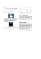
OVERVIEW: THE SR40•8 IN A NUTSHELL This section provides a quick summary of the SR40•8's major features. It is not intended to be a dissertation on how to use a mixer, especially the SR40•8, where the possibilities are endless. Just the same, it's a good place to get started. MIXING Channel controls manipulate mic/line signals in this order: phantom power, trim, polarity, low cut filter, insert, EQ, mute, fader, pan, and assignment switches. These signals are then assigned to the left, right and/or center mix, or to one of the eight subs. The main mix (left, right and center) typically feeds the main sound system. The left/ right mix can be controlled by individual faders or switched to share one fader. Subs 1-8 can be assigned to the left/right or center mix, enabling them to be used as master faders for submixes of channels. Alternatively, the subs can be used for secondary speaker systems. More output routing options involve the matrix, discussed below. MATRIX The SR40•8 has 11 primary mix buses: left, right, center, and 8 subs. Via the channel's assignment switching, signals can be distributed among these buses. If a situation demands a unique destination for each mix, the dedicated outputs for each of these mixes will suffice. More likely, a situation will demand that these 11 mixes be recombined in some way, to feed off-site systems, delay towers, assistive listening systems, or special mixes for recording or broadcast. Enter the Matrix. The matrix is simply four separate 12 x 1 mixers. Its inputs include: left, right, center, subs 1-8 and an external input at the patch panel. Each matrix strip has a level control for each of the eleven internal inputs as well as master level, solo and mute controls. STAGE MONITORS & EFFECTS Every channel, as well as each of the four main aux returns (A1-A4), has eight aux send controls. Per channel, aux sends 1-4 can be switched to be post-fader (for effects sends) or pre-EQ/pre-fader (for stage monitors). Aux sends 5-8 have a similar switch, post-fader (for effects sends) or post-EQ/pre-fader (for stage monitors with EQ). In the output section, aux sends can be routed in one of two ways. Normally, these aux mixes are controlled by the rotary master level control and mute switch, and then sent to TRS output jacks. This method is fine for effects sends or small applications. Larger installations may demand more flexibility for the stage mixes. Enter the flip switch. Each aux send master has a flip switch. This removes an aux mix from its dedicated mute switch and level control, and diverts it to the like-numbered sub routing. This way, an aux send designated for stage cueing will have its own dedicated 100mm fader, "Air" EQ, insert, and balanced XLR output. Meanwhile, a flipped aux send also diverts the sub signal to the original aux send master controls and TRS output, ensuring that sub assignments can still be used. When used for effects, aux sends are patched into the inputs of parallel effects devices, like reverb and delay units. The outputs of these devices are the origin of aux return signals. Aux return signals, or any stereo linelevel signals, can be injected into either the main aux returns or the "B" aux returns (or into pairs of channels). The main aux returns provide most of the controls present in the channels: trim, high-pass filter, EQ, mute, pan, and assign. "B" aux returns B1, B2, and B3 are dedicated to the left/right mix and offer only rotary level and mute switch controls. (Aux return B4 is dedicated to the center mix.) Additionally, there are two stereo line-level RCA tape returns, dedicated to the left/right mix, with level control and mute switch. 10
-
 1
1 -
2
-
3
-
4
-
 5
5 -
 6
6 -
 7
7 -
 8
8 -
 9
9 -
 10
10 -
 11
11 -
 12
12 -
 13
13 -
 14
14 -
 15
15 -
16
-
17
-
18
-
19
-
20
-
21
-
22
-
23
-
24
-
25
-
26
-
27
-
28
-
29
-
30
-
31
-
32
-
33
-
34
-
35
-
36
-
37
-
38
-
39
-
40
-
41
-
42
-
43
-
44
-
45
-
46
-
47
-
48
-
49
-
50
-
51
-
52
-
53
-
54
-
55
-
56
-
57
-
58
-
59
-
60
-
61
-
62
-
63
-
64
-
65
-
66
-
67
-
68
-
69
-
70
-
71
-
72
-
73
-
74
-
75
-
76
-
77
-
78
-
79
-
80
-
81
-
82
-
83
-
84
-
85
-
86
 |
 |
