Mackie SR408 / SR568 Owner's Manual - Page 38
Dimmer, Power Supply Status, Talkback
 |
View all Mackie SR408 / SR568 manuals
Add to My Manuals
Save this manual to your list of manuals |
Page 38 highlights
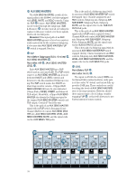
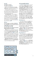
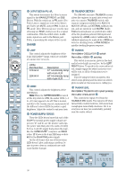
OO OO OO OO OO MAX RECEIVE IGNORE CALL COMMUNICATIONS MAX LEVEL ON 400Hz PINK NOISE OSCILLATOR TALKBACK MIC MAX TALKBACK LEVEL MATRIX A AUX 1-4 MATRIX B AUX 5-8 MATRIX C EXTERNAL MATRIX D L/R ASSIGN TALKBACK MAX SOLO LEVEL MAX PHONES INTERCOM TALKBACK CO C OS OUTPUT SECTION PFL/AFL This switch determines the Meter's source signal for the MAIN/LEFT/RIGHT and SUB Meters. With the switch up, in PFL mode (PreFader Listen), signals are sent to the Meters pre-Fader, pre-MUTE, and pre-PAN. In fact, in PFL mode, these Meters may save you the time of having use SOLO, if all you need is a signal confirmation. With the switch down, in AFL mode, signals are sent to the Meters postFader, representing the output of the circuit. DIMMER TALKBACK SECTION The SR40•8's extensive TALKBACK section allows the engineer to speak into several outputs via a master TALKBACK switch, with separate assignment switches for AUX 1-4, AUX 5-8, L/R mix, an EXTERNAL talkback output, and one switch for each MATRIX (A-D). Talkback microphones are patched into either of the two phantom-powered XLR inputs and regulated by a LEVEL control. Additionally, the talkback signal may be replaced by a 400Hz sine wave for checking levels, or PINK NOISE for quickly checking frequency response. LAMP This control adjusts the brightness of the 4-pin XLR Littlite® lamps, which are available at a music store near you. Littlite Part Number 12X-HI-4 18X-HI-4 Description 12" Hi-intensity lamp with 4-pin XLR 18" Hi-intensity lamp with 4-pin XLR METER This control adjusts the brightness of the LED Meters. Note: When the METER DIMMER is turned all the way down to LOW, the amber LEDs (+4 to +10) may appear to be off. This is normal, and due to the varying current requirements of the different colored LEDs to produce equal brightness. Adjust the control to suit your taste. POWER SUPPLY STATUS These five LEDs let you know that each of the SR40•8's essential power supply voltages are present. V.+ and V.- are the positive and negative power rails that power the audio circuitry. 5 V is a 5-volt DC supply that powers the logic, like the ULTRA MUTE™ computer and SOLO relays. 12 V powers the 4-pin XLR lamp sockets. 48 V is the PHANTOM power supply. On the off chance that one of these status LEDs doesn't glow, indicating a problem, be sure to power down as continued use could cause further damage. TALKBACK Point Before: OSCILLATOR switch. Point After: ASSIGN switches. This switch is enormous, glows in the dark, and is located right in your face, by the LEFT/ RIGHT Faders. To speak to the crew and/or talent, simply engage the switch and your voice will be sent to all the destinations you've assigned. If you're using the intercom system, this switch stops glowing and the intercom switch glows to indicate that someone is calling you. TALKBACK LEVEL Point Before: TALKBACK MIC inputs' preamp Point After: OSCILLATOR . This controls the signal level from the TALKBACK MIC inputs. The signal is off when turned fully counterclockwise, with more than enough gain turned fully clockwise. Set it so everyone can hear you comfortably, probably near the center detent. DIMMER LOW MAX LAMP LOW MAX METER METERING INPUT SECTION OUTPUT SECTION PFL PFL AFL AFL POWER SUPPLY STATUS V.+ V.- 5 V 12 V 48 V 38
-
 1
1 -
2
-
3
-
4
-
5
-
6
-
7
-
8
-
9
-
10
-
11
-
12
-
13
-
14
-
15
-
16
-
17
-
18
-
19
-
20
-
21
-
22
-
23
-
24
-
25
-
26
-
27
-
28
-
29
-
30
-
31
-
32
-
 33
33 -
 34
34 -
 35
35 -
 36
36 -
 37
37 -
 38
38 -
 39
39 -
 40
40 -
 41
41 -
 42
42 -
 43
43 -
44
-
45
-
46
-
47
-
48
-
49
-
50
-
51
-
52
-
53
-
54
-
55
-
56
-
57
-
58
-
59
-
60
-
61
-
62
-
63
-
64
-
65
-
66
-
67
-
68
-
69
-
70
-
71
-
72
-
73
-
74
-
75
-
76
-
77
-
78
-
79
-
80
-
81
-
82
-
83
-
84
-
85
-
86
 |
 |
