Mackie SR408 / SR568 Owner's Manual - Page 41
Matrix
 |
View all Mackie SR408 / SR568 manuals
Add to My Manuals
Save this manual to your list of manuals |
Page 41 highlights
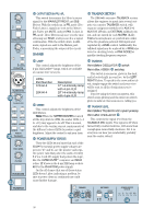
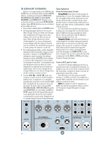
MATRIX The MATRIX can be used to create special mixes for recording, delay towers, lobby, backstage, nursery "cry" rooms, audio-for-video feeds, ADA systems, and the like. Think of it as a "mixer within a mixer." Although it may look complicated, the MATRIX is simply four separate 12 x 1 mixers. Its inputs include the eleven mixes: LEFT, RIGHT, CTR, and SUBS 1-8. Additionally, each MATRIX has an external MATRIX INPUT . Each MATRIX strip has an input level control for each of the 11 internal inputs as well as MASTER level, MUTE and SOLO controls. The external MATRIX INPUTS have no independent level controls, but are controlled by the MATRIX's MASTER level. INPUT LEVEL Point Before: Respective mix outputs (LEFT/ RIGHT/CENTER mixes and SUB 1-8 mixes .) Point After: MATRIX mixes A, B, C, and D. Each MATRIX has a column of 11 rotary controls. Adjacent to each of MATRIX A's controls is the name of the mix output feeding each MATRIX: SUB 1, SUB 2, SUB 3, SUB 4, SUB 5, SUB 6, SUB 7, SUB 8, CTR, LEFT, and RIGHT. (CTR is an abbreviation for "CENTER.") Each control is off with the knob turned fully counterclockwise, with unity gain at the "U" center detent, and provides 10dB gain turned fully up. Creating a MATRIX mix couldn't be easier. Simply adjust the input level controls as needed for each mix as it feeds each MATRIX. For instance, using MATRIX A and MATRIX B to create a stereo mix, use the MATRIX A controls for all the "left" mixes (usually LEFT, SUB 1, SUB 3, SUB 5, and SUB 7) and the MATRIX B controls for the "right" mixes (usually RIGHT, SUB 2, SUB 4, SUB 6, and SUB 8). If the ultimate destination for a MATRIX output is a device with RCA inputs, like a cassette deck, we suggest that you use MATRIX C and MATRIX D, since they have RCA outputs (TAPE B OUTPUT ), in addition to the XLR outputs. MUTE Point Before: MATRIX mix. Point After: MATRIX MASTER level . Muting removes the signal from its MATRIX OUTPUT and AFL SOLO. The PFL SOLO and PFL Meter paths are not affected. Pressing the switch toggles the electronic mute relay in the signal path's circuitry. If the signal is muted, pressing the switch un-mutes it, and vice versa. An LED adjacent to the switch glows when muted. With ULTRA MUTE™, up to ten Banks of ten different Mute Groups can be configured, enabling you to mute several signal paths at once. Not only that, but you can automate the muting of all the signal paths via an external MIDI sequencer or via the RS-232 DATA port connected to a computer. We'll discuss all this in detail later on . MASTER LEVEL Point Before: MUTE switch. Point After: MATRIX OUTPUTS , (AFL) SOLO . Use this control to set or ride the overall level of each MATRIX. The signal is off with the rotary MASTER level control turned fully counterclockwise, unity gain is at the center "U" detent, and turned fully up provides 10dB gain. SOLO PFL Point Before: MATRIX mix. PFL Point After: SOLO (MASTER controls) PFL mix (mono). AFL Point Before: MASTER level . AFL Point After: SOLO (MASTER controls) AFL mix (stereo). SOLO allows you to audition signals through your headphones without having to assign them to any of the LEFT/RIGHT/CENTER mixes or subgroups (SUB 1-8 mixes) . You can simultaneously SOLO as many signals as you like. The SR40•8 features nondestructive solo: Engaging SOLO does not interrupt any of the other Channels, buses, or outputs. Not only that, the SOLO system comes in two flavors: PFL (Pre-Fader Listen) and AFL (After-Fader Listen, Solo-In-Place). OO OO OO OO OO OO OO OO OO OO OO OO U SUB 1 +10 U SUB 2 +10 U SUB 3 +10 U SUB 4 +10 U SUB 5 +10 U SUB 6 +10 U SUB 7 +10 U SUB 8 +10 U CTR +10 U LEFT +10 U RIGHT +10 MATRIX A A MUTE A U +10 MASTER SOLO 41
-
 1
1 -
2
-
3
-
4
-
5
-
6
-
7
-
8
-
9
-
10
-
11
-
12
-
13
-
14
-
15
-
16
-
17
-
18
-
19
-
20
-
21
-
22
-
23
-
24
-
25
-
26
-
27
-
28
-
29
-
30
-
31
-
32
-
33
-
34
-
35
-
 36
36 -
 37
37 -
 38
38 -
 39
39 -
 40
40 -
 41
41 -
 42
42 -
 43
43 -
 44
44 -
 45
45 -
 46
46 -
47
-
48
-
49
-
50
-
51
-
52
-
53
-
54
-
55
-
56
-
57
-
58
-
59
-
60
-
61
-
62
-
63
-
64
-
65
-
66
-
67
-
68
-
69
-
70
-
71
-
72
-
73
-
74
-
75
-
76
-
77
-
78
-
79
-
80
-
81
-
82
-
83
-
84
-
85
-
86
 |
 |
