Mackie SR408 / SR568 Owner's Manual - Page 37
Monitor, Left/right/center Meters, Metering
 |
View all Mackie SR408 / SR568 manuals
Add to My Manuals
Save this manual to your list of manuals |
Page 37 highlights
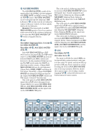
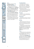
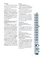
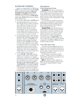
MONITOR MONITOR signals are a line-level equivalent of the HEADPHONES output. The TRS MONITOR outputs are designed for special situations such as these: You can use these jacks to deliver the FOH (front-of-house) headphone mix to an engineer operating a secondary stage monitor console. If you want to drive several pairs of headphones via an outboard amplifier, patch these outputs to that amp. If the console is in a soundproof room, as in live sound-studio work or studio recording/ mixdown, patch the MONITOR outputs to your control room amplifier and speakers. LINE OUT (LEVEL) Point Before: INSERT (HEADPHONES) . Point After: MONITOR outputs. Just like the HEADPHONES, the MONITOR outputs always receive the LEFT/RIGHT mix, with the CENTER mix blended into each side. This control sets the level for those signals, and it follows the PHONES level control, meaning that the level at these outputs is controlled twice - by the PHONES level and by the LINE OUT control. SOLO signals to the MONITOR outputs are controlled by SOLO LEVEL and this MONITOR LINE OUT level - the PHONES level has no effect on SOLO signals. This is so you can tailor the "mix level" (non-SOLO signals) and the SOLO LEVEL independently. MUTE This switch is your garden-variety DPDT (double-pole, double-throw) switch. Engage it and the line-level MONITOR outputs become silent. The MONITOR MUTE is not a member of the ULTRA MUTE™ system and therefore cannot be remotely controlled. LEFT/RIGHT/CENTER METERS These individual Meters give you constant visual information about the signal level in that mix. With the METERING: OUTPUT SECTION PFL/AFL switch set to PFL (up), the Meters display the pre-Fader signal of the mix. With the switch down, the Meters display the post-Fader output of the mix. These three Meters, unlike the other fiftysix, have a secondary purpose - to display SOLO levels. Whenever SOLO is engaged, all three Meters' inputs change from the LEFT/ CENTER/RIGHT mix signals to the SOLO signals. The PFL SOLO signal will appear on the CENTER Meter and the AFL signals appear on the LEFT/RIGHT Meters. A 0dB reading on the Meters represents a 0dBu output signal, when the METERING: OUTPUT SECTION PFL/AFL switch is engaged (AFL). In other words, 0VU=0dBu. METERING INPUT SECTION PFL/AFL This switch determines the Meter's source signal for the Channels and the MAIN AUX RETURN (A1-A4). With the switch up, in PFL mode (Pre-Fader Listen), signals are sent to the Meters pre-Fader, pre-MUTE, and pre-PAN. In fact, in PFL mode, these Meters may save you the time of having to use SOLO, if all you need is a signal confirmation. With the switch down, in AFL mode, signals will be sent to the Meters post-Fader, representing the output of the circuit. With this switch set to PFL, you can perform on-the-fly TRIM settings, as explained in the Turbo Method of the LevelSetting Procedure . OO TAPE RETURNS U U RUDE U SOLO LIGHT +15 LEVEL MUTE SOLO TAPE A OO +15 LEVEL OO +15 LINE OUT MUTE SOLO TAPE B MUTE MONITOR PFL AFL INPUTS PFL AFL OUTPUTS SOLO DIMMER LOW MAX LAMP LOW MAX METER METERING INPUT SECTION OUTPUT SECTION PFL PFL AFL AFL POWER SUPPLY STATUS V.+ V.- 5 V 12 V 48 V 37
-
 1
1 -
2
-
3
-
4
-
5
-
6
-
7
-
8
-
9
-
10
-
11
-
12
-
13
-
14
-
15
-
16
-
17
-
18
-
19
-
20
-
21
-
22
-
23
-
24
-
25
-
26
-
27
-
28
-
29
-
30
-
31
-
 32
32 -
 33
33 -
 34
34 -
 35
35 -
 36
36 -
 37
37 -
 38
38 -
 39
39 -
 40
40 -
 41
41 -
 42
42 -
43
-
44
-
45
-
46
-
47
-
48
-
49
-
50
-
51
-
52
-
53
-
54
-
55
-
56
-
57
-
58
-
59
-
60
-
61
-
62
-
63
-
64
-
65
-
66
-
67
-
68
-
69
-
70
-
71
-
72
-
73
-
74
-
75
-
76
-
77
-
78
-
79
-
80
-
81
-
82
-
83
-
84
-
85
-
86
 |
 |
