Netgear GSM7252PS 7000 Series Managed Switch Administration Guide for Software
Netgear GSM7252PS - ProSafe 52 Ports Gigabit Ethernet L2 Managed Stackable Switch Manual
 |
UPC - 606449071665
View all Netgear GSM7252PS manuals
Add to My Manuals
Save this manual to your list of manuals |
Netgear GSM7252PS manual content summary:
- Netgear GSM7252PS | 7000 Series Managed Switch Administration Guide for Software - Page 1
ProSafe 7000 Managed Switch Software Administration Manual, Release 8.0.3 NETGEAR, Inc. 350 East Plumeria Drive San Jose, CA 95134 202-10515-03 June 2010 v1.0 - Netgear GSM7252PS | 7000 Series Managed Switch Administration Guide for Software - Page 2
product(s) or circuit layout(s) described herein. Netgear's 7000 Series Managed Switch is compliant with the following EU Council Setup Guide. Software release 8.0.2: new firmware with DHCP L3 Relay, color conform policy, DHCP Server in dynamic mode, and configuring a stacking port as an Ethernet - Netgear GSM7252PS | 7000 Series Managed Switch Administration Guide for Software - Page 3
Contents About This Manual Chapter 1 Virtual LANs Create Two VLANs ...1-2 Assign Ports to VLAN2 1-4 Assign Ports to VLAN3 1-5 Assign VLAN3 as the Default VLAN for Port 1/0/2 1-7 Creating a MAC-based VLAN 1-8 Create a Protocol-Based VLAN 1-12 Virtual VLANs: Create an IP Subnet Based VLAN 1-15 - Netgear GSM7252PS | 7000 Series Managed Switch Administration Guide for Software - Page 4
ProSafe 7000 Managed Switch Software Administration Manual, Release 8.0.3 VLAN Routing RIP Configuration 5-8 Chapter 6 OSPF Configure an Inter-Area Router 6-2 Configure OSPF on a Border Router 6-8 Configure Area 1 as a Stub Area 6-15 Configure Area 1 as a nssa Area 6-24 VLAN Routing OSPF - Netgear GSM7252PS | 7000 Series Managed Switch Administration Guide for Software - Page 5
ProSafe 7000 Managed Switch Software Administration Manual address-table igmpsnooping 12-3 Configure the Switch with an External Multicast Router 12-4 Configure the Switch with a Multicast Router Configure the Maximum Rate of DHCP Messages 13-49 IP Source Guard ...13-51 Chapter 14 Simple Network - Netgear GSM7252PS | 7000 Series Managed Switch Administration Guide for Software - Page 6
-16 Stack the Switches using 10G fiber 17-20 Chapter 18 SNMP Add a New Community 18-1 Enable SNMP Trap ...18-2 Configure SNMP V3 ...18-3 sFlow ...18-5 Configure Time-Based Sampling of Counters with sFlow 18-9 Chapter 19 DNS Specify Two DNS Servers 19-1 Manually Add a Host Name and an IP Address - Netgear GSM7252PS | 7000 Series Managed Switch Administration Guide for Software - Page 7
ProSafe 7000 Managed Switch Software Administration Manual, Release 8.0.3 Chapter 20 DHCP Server Configure a DHCP MLD ...29-1 MLD Snooping ...29-19 Chapter 30 DVMRP Configure DVMRP on a NETGEAR Switch 30-1 Chapter 31 Captive Portal Captive Portal Configuration 31-2 Enable Captive Portal 31-2 - Netgear GSM7252PS | 7000 Series Managed Switch Administration Guide for Software - Page 8
ProSafe 7000 Managed Switch Software Administration Manual, Release 8.0.3 Block a Captive Portal Instance 31-5 Local Authorization User/Group Configuration 31-6 Remote Authorization (RADIUS) User Configuration 31-8 SSL Certificates ...31-10 Index x v1.0, June 2010 - Netgear GSM7252PS | 7000 Series Managed Switch Administration Guide for Software - Page 9
the platform specific functionality of the Switching, Routing, SNMP, Config, Management, and other packages. In addition, see the following publications: • The NETGEAR installation guide for your switch • Hardware Installation Guide • Software Setup Guide • NETGEAR CLI Reference for the Prosafe 7X00 - Netgear GSM7252PS | 7000 Series Managed Switch Administration Guide for Software - Page 10
VLAN3 as the Default VLAN for Port 1/0/2" on page 1-7 • "Creating a MAC-based VLAN" on page 1-8 • "Create a Protocol-Based VLAN" on page 1-12 • "Virtual VLANs: Create an IP Subnet Based VLAN" on page 1-15 • "Voice VLAN" on page 1-19 Adding Virtual LAN (VLAN) support to a Layer 2 switch offers some - Netgear GSM7252PS | 7000 Series Managed Switch Administration Guide for Software - Page 11
ProSafe 7000 Managed Switch Software Administration Manual, Release 8.0.3 use to configure the switch as shown in the diagram. Layer 3 Switch Port 1/0/2 VLAN Router Port 1/3/1 192.150.3.1 Port 1/0/3 VLAN Router Port 1/3/2 192.150.4.1 Port 1/0/1 Layer 2 Switch Layer 2 Switch VLAN 10 VLAN 20 - Netgear GSM7252PS | 7000 Series Managed Switch Administration Guide for Software - Page 12
ProSafe 7000 Managed Switch Software Administration Manual, Release 8.0.3 1. Create VLAN 2. a. From the main menu, select Switching > VLAN >Basic > VLAN configuration. A screen similar to the following displays. Figure 1-2 b. Enter the following information in the VLAN Configuration. • In the VLAN - Netgear GSM7252PS | 7000 Series Managed Switch Administration Guide for Software - Page 13
ProSafe 7000 Managed Switch Software Administration Manual, Netgear Switch) #config (Netgear Switch) (Config)#interface range 1/0/1-1/0/2 (Netgear Switch) (conf-if-range-1/0/1-1/0/2)#vlan participation include 2 (Netgear Switch) (conf-if-range-1/0/1-1/0/2)#vlan acceptframe vlanonly (Netgear Switch - Netgear GSM7252PS | 7000 Series Managed Switch Administration Guide for Software - Page 14
ProSafe 7000 Managed Switch Software Administration Manual, Release 8.0.3 c. Click the Unit 1. The Ports display. d. Click frames will be accepted on port 1/0/1 and 1/0/2. a. From the main menu, select Switching > VLAN> Advanced > Port PVID Configuration. A screen similar to the following displays. - Netgear GSM7252PS | 7000 Series Managed Switch Administration Guide for Software - Page 15
ProSafe 7000 Managed Switch Software Administration Manual, Release 8.0.3 CLI: Assigning Ports to VLAN3 (Netgear Switch) (Config)#interface range 1/0/2-1/0/4 (Netgear Switch) (conf-if-range-1/0/2-1/0/4)#vlan participation include 3 (Netgear Switch) (conf-if-range-1/0/2-1/0/4)#exit (Netgear Switch) ( - Netgear GSM7252PS | 7000 Series Managed Switch Administration Guide for Software - Page 16
VLAN for port 1/0/2. CLI: Assigning VLAN3 as the Default VLAN for Port 1/0/2 (Netgear Switch) #config (Netgear Switch) (Config)#interface 1/0/2 (Netgear Switch) (Interface 1/0/2)#vlan pvid 3 (Netgear Switch) (Interface 1/0/2)#exit (Netgear Switch) (Config)#exit Web Interface: Assigning VLAN3 as the - Netgear GSM7252PS | 7000 Series Managed Switch Administration Guide for Software - Page 17
ProSafe 7000 Managed Switch Software Administration Manual, Release 8.0.3 a. From the main menu, select Switching > VLAN >Advanced > Port PVID Configuration. A screen similar to the following displays. Figure 1-8 b. Under PVID Configuration, scroll down to interface 1/0/2 and select the checkbox - Netgear GSM7252PS | 7000 Series Managed Switch Administration Guide for Software - Page 18
ProSafe 7000 Managed Switch Software Administration Manual, Release 8.0.3 MAC based VLAN feature allows incoming untagged packets to be assigned to a VLAN and thus classify traffic based on the source MAC address of the packet. A MAC to VLAN mapping is defined by configuring an entry in the MAC to - Netgear GSM7252PS | 7000 Series Managed Switch Administration Guide for Software - Page 19
ProSafe 7000 Managed Switch Software Administration Manual, Release 8.0.3 Web Interface Procedure: Assigning a MAC-Based VLAN To use the Web interface to configure the managed switch, proceed as follows: 1. Create VLAN 3. a. From the main menu, select Switching > VLAN >Basic > VLAN configuration. A - Netgear GSM7252PS | 7000 Series Managed Switch Administration Guide for Software - Page 20
ProSafe 7000 Managed Switch Software Administration Manual, Release 8.0.3 b. Select 3 in the VLAN ID field. c. Click the Unit 1. The Ports display. d. Click the gray box before the Unit 1until U displays. e. Click Apply 3. Assign VPID 3 to the port 1/0/23. a. From the main menu, select Switching > - Netgear GSM7252PS | 7000 Series Managed Switch Administration Guide for Software - Page 21
ProSafe 7000 Managed Switch Software Administration Manual, Release 8.0.3 b. Enter the following information in the MAC Based VLAN Configuration. • Enter 00:00:0A:00:00:02 in the MAC Address field. • Enter 3 in the PVID(1 to 4093) field. c. Click Add. Create a Protocol-Based VLAN Create two protocol - Netgear GSM7252PS | 7000 Series Managed Switch Administration Guide for Software - Page 22
ProSafe 7000 Managed Switch Software Administration Manual, Release 8.0.3 Enable protocol vlan group 1 and 2 on the interface. (Netgear Switch)(Vlan)#exit (Netgear Switch)#config (Netgear Switch)(Config)#interface 1/0/11 (Netgear Switch)(Interface 1/0/11)#protocol vlan group 1 (Netgear Switch)( - Netgear GSM7252PS | 7000 Series Managed Switch Administration Guide for Software - Page 23
ProSafe 7000 Managed Switch Software Administration Manual, Release 8.0.3 a. From the main menu, select Switching > VLAN >Advanced IP and ARP while holding down the Ctrl key. • In the VLAN field, enter 5. c. Click Add. 3. Add the port 11 to the group vlan_ipx. a. From the main menu, select Switching - Netgear GSM7252PS | 7000 Series Managed Switch Administration Guide for Software - Page 24
ProSafe 7000 Managed Switch Software Administration Manual, Release 8.0.3 a. From the main menu, select Switching > VLAN >Advanced addresses. IP subnet VLANs are based on layer 3 information from packet headers. The switch makes use of the network-layer address (for example, subnet address for TCP/IP - Netgear GSM7252PS | 7000 Series Managed Switch Administration Guide for Software - Page 25
VLAN PC 2 10.100.5.30 (Netgear Switch) #vlan database (Netgear Switch) (Vlan)#vlan 2000 (Netgear Switch) (Vlan)#vlan association subnet 10.100.0.0 255.255.0.0 2000 (Netgear Switch) (Vlan)#exit Create an IP subnet based VLAN 2000. (Netgear Switch) #config (Netgear Switch) (Config)#interface range - Netgear GSM7252PS | 7000 Series Managed Switch Administration Guide for Software - Page 26
ProSafe 7000 Managed Switch Software Administration Manual, Release 8.0.3 Web Interface: Creating an IP Subnet Based VLAN To use the Web interface to configure the IP subnet based VLAN, proceed as follows: 1. Create VLAN 2000. a. From the main menu, select Switching > VLAN >Basic > VLAN - Netgear GSM7252PS | 7000 Series Managed Switch Administration Guide for Software - Page 27
2000. a. From the main menu, select Switching > VLAN >Advanced->IP Subnet Based VLAN. A screen similar to the following displays. Figure 1-21 b. Enter the following information in the IP Subnet Based VLAN Configuration. • In the IP Address field, enter 10.100.0.0. • In the Subnet Mask field, enter - Netgear GSM7252PS | 7000 Series Managed Switch Administration Guide for Software - Page 28
ProSafe 7000 Managed Switch Software Administration Manual, Release 8.0.3 Voice VLAN The voice VLAN feature enables switch ports to carry voice traffic with defined priority so as to enable separation of voice and data traffic coming onto the port. Voice VLAN is to ensure that sound quality of an IP - Netgear GSM7252PS | 7000 Series Managed Switch Administration Guide for Software - Page 29
ProSafe 7000 Managed Switch Software Administration Manual, Release 8.0.3 CLI: Configuring Voice VLAN and Prioritizing Voice Traffic Create VLAN 10. (Netgear Switch) #vlan database (Netgear Switch) (Vlan)#vlan 10 (Netgear Switch) (Vlan)#exit Include the ports 1/0/1and 1/0/2 in the VLAN 10. (Netgear - Netgear GSM7252PS | 7000 Series Managed Switch Administration Guide for Software - Page 30
ProSafe 7000 Managed Switch Software Administration Manual, Release 8.0.3 Map the Policy and Class and assign to the higher priority queue. (Netgear Switch) (Config-policy-map)#class ClassVoiceVLAN (Netgear Switch) (Config-policy-classmap)#assign-queue 3 (Netgear Switch) (Config-policy-classmap)# - Netgear GSM7252PS | 7000 Series Managed Switch Administration Guide for Software - Page 31
ProSafe 7000 Managed Switch Software Administration Manual, Release 8.0.3 d. Click Add. At the end of this configuration a screen similar to the following displays. Figure 1-24 2. Include the ports 1/0/1 and 1/0/2 in the VLAN 10. a. From the main menu, select Switching > VLAN > Advanced -> VLAN - Netgear GSM7252PS | 7000 Series Managed Switch Administration Guide for Software - Page 32
ProSafe 7000 Managed Switch Software Administration Manual, Release 8.0.3 c. Select Port 1 and Port 2 as Tagged. A screen similar to the following displays. Figure 1-26 d. Click Apply. 3. Configure Voice VLAN globally. a. From the main menu, select Switching > VLAN > Advanced > Voice VLAN - Netgear GSM7252PS | 7000 Series Managed Switch Administration Guide for Software - Page 33
ProSafe 7000 Managed Switch Software Administration Manual, Release 8.0.3 c. Click Apply. A screen similar to the following displays. Figure 1-28 4. Configure Voice VLAN Mode in the interface 1/0/2. a. From the main menu, select Switching > VLAN > Advanced -> Voice VLAN Configuration. b. Select the - Netgear GSM7252PS | 7000 Series Managed Switch Administration Guide for Software - Page 34
ProSafe 7000 Managed Switch Software Administration Manual, Release 8.0.3 a. From the main menu, select QoS > Advanced > Class Configuration. A screen similar to the following displays. Figure 1-30 b. Enter Class Name as ClassVoiceVLAN. c. Select Class - Netgear GSM7252PS | 7000 Series Managed Switch Administration Guide for Software - Page 35
ProSafe 7000 Managed Switch Software Administration Manual, Release 8.0.3 b. Click the class ClassVoiceVLAN. A screen similar to the following displays. Figure 1-33 c. In the DiffServ Class Configuration table, select VLAN. d. Enter VLAN ID as - Netgear GSM7252PS | 7000 Series Managed Switch Administration Guide for Software - Page 36
ProSafe 7000 Managed Switch Software Administration Manual, Release 8.0.3 a. From the main menu, select QoS > Advanced > Policy Configuration. A screen similar to the following displays. Figure 1-36 b. Enter Policy Name as PolicyVoiceVLAN. c. Select Policy - Netgear GSM7252PS | 7000 Series Managed Switch Administration Guide for Software - Page 37
ProSafe 7000 Managed Switch Software Administration Manual, Release 8.0.3 a. From the main menu, select QoS > Advanced > Policy Configuration. A screen similar to the following displays. Figure 1-38 b. Click the Policy PolicyVoiceVLAN. A screen similar to - Netgear GSM7252PS | 7000 Series Managed Switch Administration Guide for Software - Page 38
ProSafe 7000 Managed Switch Software Administration Manual, Release 8.0.3 c. Select Assign Queue as 3. A screen similar to the following displays. Figure 1-40 d. Click Apply. 9. Assign it to the interfaces 1/0/1 and 1/0/2. a. From the main menu, select QoS > Advanced > Service Interface - Netgear GSM7252PS | 7000 Series Managed Switch Administration Guide for Software - Page 39
ProSafe 7000 Managed Switch Software Administration Manual, Release 8.0.3 c. Select Policy Name as PolicyVoiceVLAN. A screen similar to the following displays. Figure 1-42 d. Click Apply. A screen similar to the following displays. Figure 1-43 1-30 v1.0, June 2010 Virtual LANs - Netgear GSM7252PS | 7000 Series Managed Switch Administration Guide for Software - Page 40
Aggregation This chapter includes instructions for configuring Link Aggregation (LAG). The following examples are provided: • "Create Two LAGs" on page 2-2 • "Add the Ports to the LAGs" on page 2-3 • "Enable Both LAGs" on page 2-5 Link Aggregation (LAG) allows the switch to treat multiple physical - Netgear GSM7252PS | 7000 Series Managed Switch Administration Guide for Software - Page 41
Manual, Release 8.0.3 Create Two LAGs The following figure shows the example network. Port 1/0/3 LAG_10 Subnet 3 Port 1/0/2 Server LAG_10 Layer 3 Switch Port 1/0/8 LAG 20 Port 1/0/9 LAG_20 Layer 2 Switch Subnet 2 Subnet 3 Figure 2-1 CLI: Creating Two LAGs (Netgear Switch) #config (Netgear - Netgear GSM7252PS | 7000 Series Managed Switch Administration Guide for Software - Page 42
ProSafe 7000 Managed Switch Software Administration Manual, Release 8.0.3 Web Interface: Creating Two LAGs To use the Web interface to configure the managed switch, proceed as follows: 1. Create LAG lag_10. a. From the main menu, select Switching > LAG >LAG Configuration. A screen similar to the - Netgear GSM7252PS | 7000 Series Managed Switch Administration Guide for Software - Page 43
ProSafe 7000 Managed Switch Software Administration Manual, Release 8.0.3 CLI: Adding the Ports to the LAGs (Netgear Switch) #config (Netgear Switch) (Config)#interface 0/2 (Netgear Switch) (Interface 0/2)#addport 1/1 (Netgear Switch) (Interface 0/2)#exit (Netgear Switch) (Config)#interface 0/3 ( - Netgear GSM7252PS | 7000 Series Managed Switch Administration Guide for Software - Page 44
ProSafe 7000 Managed Switch Software Administration Manual, Release 8.0.3 e. Click Apply to save the settings. 2. Add ports to the lag_20. a. From the main menu, select Switching a Web interface procedure. CLI: Enabling Both LAGs By default, the system enables link trap notification (Console) #config - Netgear GSM7252PS | 7000 Series Managed Switch Administration Guide for Software - Page 45
ProSafe 7000 Managed Switch Software Administration Manual, Release 8.0.3 Web Interface: Enabling Both LAGs To use the Web interface to configure the switch, proceed as follows: a. From the main menu, select Switching > LAG >LAG Configuration. A screen similar to the following displays. Figure 2-6 - Netgear GSM7252PS | 7000 Series Managed Switch Administration Guide for Software - Page 46
port • Update the Layer 3 header • Recreate the Layer 2 header The router's IP address is often statically configured in the end station, although the 7000 Series Managed Switch supports protocols such as DHCP that allow the address to be assigned dynamically. Likewise, you may assign some of the - Netgear GSM7252PS | 7000 Series Managed Switch Administration Guide for Software - Page 47
ProSafe 7000 Managed Switch Software Administration Manual, Release 8.0.3 • IP Forwarding, responsible for forwarding received IP packets. • ARP Mapping, responsible for maintaining the ARP Table used to correlate IP and MAC addresses. The table contains both static entries and entries dynamically - Netgear GSM7252PS | 7000 Series Managed Switch Administration Guide for Software - Page 48
ProSafe 7000 Managed Switch Software Administration Manual, Release 8.0.3 CLI: Enabling Routing for the Switch Use the following command to enable routing for the switch. Execution of the command enables IP forwarding by default. (Netgear Switch) #config (Netgear Switch) (Config)#ip routing (Netgear - Netgear GSM7252PS | 7000 Series Managed Switch Administration Guide for Software - Page 49
ProSafe 7000 Managed Switch Software Administration Manual, Release 8.0.3 CLI: Enabling Routing for Ports on the Switch (Netgear Switch) #config (Netgear Switch) (Config)#interface 1/0/2 (Netgear Switch) (Interface 1/0/2)#routing (Netgear Switch) (Interface 1/0/2)#ip address 192.150.2.1 255.255.255 - Netgear GSM7252PS | 7000 Series Managed Switch Administration Guide for Software - Page 50
ProSafe 7000 Managed Switch Software Administration Manual, Release 8.0.3 • In the IP Address field, enter 192.150.2.1. • In the Subnet Mask field, enter 255.255.255.0. • Select Enable in Routing Mode field. d. Click Apply to save the settings. 2. Assign IP address 192.150.3.1/24 to the interface - Netgear GSM7252PS | 7000 Series Managed Switch Administration Guide for Software - Page 51
the switch to forward the packet based on the destination IP address. The route entry in the route table can either be created dynamically via routing protocols like RIP and OSPF, or can be manually created by the network administrator. The routes created manually is called either static or default - Netgear GSM7252PS | 7000 Series Managed Switch Administration Guide for Software - Page 52
ProSafe 7000 Managed Switch Software Administration Manual, Release 8.0.3 CLI: Add a Default Route (FSM7338S) (Config) #ip route default ? Enter the IP Address of the next router. (FSM7328S) (Config)#ip route default 10.10.10.2 Note that IP subnet "10.10.10.0" should be configured via - Netgear GSM7252PS | 7000 Series Managed Switch Administration Guide for Software - Page 53
Procedure: The following commands assume the switch has already defined a routing interface with network address of 10.10.10.0, and configured that all packets destined for network 10.10.100.0 take the path of routing port. (FSM7328S) #show ip route Total Number of Routes 1 Network Subnet - Netgear GSM7252PS | 7000 Series Managed Switch Administration Guide for Software - Page 54
ProSafe 7000 Managed Switch Software Administration Manual, Release 8.0.3 2. Select Static in the Route Type field. 3. Enter Network Address field. Noted this field is expecting a network IP address, not a host IP address. Do not put down something like "10,100.100 static or default, simply check - Netgear GSM7252PS | 7000 Series Managed Switch Administration Guide for Software - Page 55
can configure the 7000 Series Managed Switch with some ports supporting VLANs and some supporting routing. You can also configure it to allow traffic on a VLAN to be treated as if the VLAN were a router port. When a port is enabled for bridging (the default) rather than routing, all normal bridge - Netgear GSM7252PS | 7000 Series Managed Switch Administration Guide for Software - Page 56
you would use to configure a 7000 Series Managed Switch to provide the VLAN routing support shown in the diagram. Layer 3 Switch Port 1/0/2 VLAN Router Port 1/3/1 192.150.3.1 Port 1/0/3 VLAN Router Port 1/3/2 192.150.4.1 Port 1/0/1 Layer 2 Switch Layer 2 Switch VLAN 10 VLAN 20 Figure 4-1 CLI - Netgear GSM7252PS | 7000 Series Managed Switch Administration Guide for Software - Page 57
ProSafe 7000 Managed Switch Software Administration Manual, Release 8.0.3 Web Interface: Creating Two VLANs To use the Web interface to configure the managed switch, proceed as follows: 1. Create VLAN 10, VLAN20. a. From the main menu, select Switching > VLAN >Advanced > VLAN configuration. A screen - Netgear GSM7252PS | 7000 Series Managed Switch Administration Guide for Software - Page 58
ProSafe 7000 Managed Switch Software Administration Manual, Release 8.0.3 h. In the VLAN Name field, enter VLAN20. i. Select Static in the VLAN Type field. j. Click Add. 2. Add ports to the VLAN10 and VLAN20. a. From the main menu, select Switching > VLAN >Advanced > VLAN Membership. A screen - Netgear GSM7252PS | 7000 Series Managed Switch Administration Guide for Software - Page 59
ProSafe 7000 Managed Switch Software Administration Manual, Release 8.0.3 g. Select 20 in the VLAN ID field. h. Click Apply 3. Assign PVID to the VLAN10 and VLAN20. a. From the main menu, select Switching > VLAN> Advanced > Port PVID Configuraton. A screen similar to the following displays. Figure - Netgear GSM7252PS | 7000 Series Managed Switch Administration Guide for Software - Page 60
ProSafe 7000 Managed Switch Software Administration Manual, Release 8.0.3 f. From the main menu, select Switching > VLAN> Advanced > Port PVID for the VLANs: (Netgear Switch) #vlan data (Netgear Switch) (Vlan)#vlan routing 10 (Netgear Switch) (Vlan)#vlan routing 20 (Netgear Switch) (Vlan)#exit - Netgear GSM7252PS | 7000 Series Managed Switch Administration Guide for Software - Page 61
Administration Manual, Release 8.0.3 Enable routing for the switch: (Netgear Switch) #config (Netgear Switch) (Config)#ip routing (Netgear Switch) (Config)#exit The next sequence shows an example of configuring the IP addresses and subnet masks for the virtual router ports. (Netgear Switch) (Config - Netgear GSM7252PS | 7000 Series Managed Switch Administration Guide for Software - Page 62
ProSafe 7000 Managed Switch Software Administration Manual, Release 8.0.3 4. From the main menu, select Routing > VLAN> VLAN the following information. • Select 10 in the VLAN ID(1 to 4093) field. • In the IP Address field, enter 192.150.4.1. • In the Subnet Mask filed, enter 255.255.255.0. 6. Click - Netgear GSM7252PS | 7000 Series Managed Switch Administration Guide for Software - Page 63
RIPv2 defined in RFC 1723 - Route specification is extended to include subnet mask and gateway - The routing table is sent to a multicast address, reducing network traffic - An authentication method is used for security The 7000 Series Managed Switch supports both versions of RIP. You may configure - Netgear GSM7252PS | 7000 Series Managed Switch Administration Guide for Software - Page 64
ProSafe 7000 Managed Switch Software Administration Manual, Release 8.0.3 The configuration commands used in the following example enable RIP on ports 1/0/2 and 1/0/3 as shown in the network illustrated in Figure 5-1 Layer 3 Switch acting as a router Port 1/0/2 192.150.2.2 Port 1/0/5 192.64.4.1 - Netgear GSM7252PS | 7000 Series Managed Switch Administration Guide for Software - Page 65
and assigns IP addresses for ports 1/0/2 and 1/0/3. (Netgear Switch) #config (Netgear Switch) (Config)#interface 1/0/2 (Netgear Switch) (Interface 1/0/2)#routing (Netgear Switch) (Interface 1/0/2)#ip address 192.150.2.1 255.255.255.0 (Netgear Switch) (Interface 1/0/2)#exit (Netgear Switch) (Config - Netgear GSM7252PS | 7000 Series Managed Switch Administration Guide for Software - Page 66
ProSafe 7000 Managed Switch Software Administration Manual, Release 8.0.3 a. From the main menu, select Routing > Advanced >IP Interface Configuration. A screen similar to the following displays. Figure 5-3 b. Under IP IP Interface Configuration, enter the following information. • In the IP Address - Netgear GSM7252PS | 7000 Series Managed Switch Administration Guide for Software - Page 67
. • In the IP Address field, enter 192.150.3.1. • In the Subnet Mask, enter 255.255.255.0. • Select Enable in the Routing Mode field. d. Click Apply to save the settings. Enable RIP for the Switch Note: This step can be skipped since the RIP is enabled by default. 5-5 Routing Information - Netgear GSM7252PS | 7000 Series Managed Switch Administration Guide for Software - Page 68
ProSafe 7000 Managed Switch Software Administration Manual, Release 8.0.3 CLI: Enabling RIP for the Switch The next sequence enables RIP for the switch. the route preference defaults to 15. (Netgear Switch) #config (Netgear Switch) (Config)#router rip (Netgear Switch) (Config router)#enable (Netgear - Netgear GSM7252PS | 7000 Series Managed Switch Administration Guide for Software - Page 69
ProSafe 7000 Managed Switch Software Administration Manual, Release 8.0.3 but send only RIPv2 formatted frames. (Netgear Switch) #config (Netgear Switch) (Config)#interface 1/0/2 (Netgear Switch) (Interface 1/0/2)#ip rip (Netgear Switch) (Interface 1/0/2)#ip rip receive version both (Netgear Switch) - Netgear GSM7252PS | 7000 Series Managed Switch Administration Guide for Software - Page 70
ProSafe 7000 Managed Switch Software Administration Manual, Release 8.0.3 4. From the main menu, select Routing > RIP > routers after 180 seconds, and removed from their tables after an additional 120 seconds. There are two versions of RIP: • RIPv1 defined in RFC 1058 - Routes are specified by IP - Netgear GSM7252PS | 7000 Series Managed Switch Administration Guide for Software - Page 71
ProSafe 7000 Managed Switch Software Administration Manual, Release 8.0.3 • RIPv2 defined in RFC 1723 - Route specification is extended to include subnet mask and gateway - The routing table is sent to a multicast address, reducing network traffic - An authentication method is used for security The - Netgear GSM7252PS | 7000 Series Managed Switch Administration Guide for Software - Page 72
will default to 15. (Netgear Switch) (Config)#router rip (Netgear Switch) (Config router)#enable (Netgear Switch) (Config router)#exit Configure the IP address and subnet mask for a non-virtual router port. (Netgear Switch) (Config)#interface 1/0/5 (Netgear Switch) (Interface 1/0/5)#ip address 192 - Netgear GSM7252PS | 7000 Series Managed Switch Administration Guide for Software - Page 73
ProSafe 7000 Managed Switch Software Administration Manual, Release 8.0.3 Enable RIP for the VLAN router ports. Authentication will default to none, and no default route entry will be created. (Netgear Switch) (Config)#interface vlan 10 (Netgear Switch) (Interface vlan 10)#ip rip (Netgear Switch) ( - Netgear GSM7252PS | 7000 Series Managed Switch Administration Guide for Software - Page 74
Switch Software Administration Manual, Release 8.0.3 a. From the main menu, select Routing > VLAN > VLAN Routing Wizard. A screen similar to the following displays. Figure 5-10 b. Enter the following information in the VLAN Routing Wizard: • In the Vlan ID field, enter 20. • In the IP Address - Netgear GSM7252PS | 7000 Series Managed Switch Administration Guide for Software - Page 75
ProSafe 7000 Managed Switch Software Administration Manual, Release 8.0.3 a. From the main menu, select Routing > RIP > Advanced>RIP Configuration. A screen similar to the following displays. Figure 5-12 b. Under the Interface Configuration, enter the - Netgear GSM7252PS | 7000 Series Managed Switch Administration Guide for Software - Page 76
and destination address are in the same area, and inter-area routing across an OSPF backbone is used when they are not. An inter-area router communicates with border routers in each of the areas to which it provides connectivity. The 7000 Series Managed Switch operating as a router and running - Netgear GSM7252PS | 7000 Series Managed Switch Administration Guide for Software - Page 77
1/0/2 192.150.2.1 Port 1/0/3 192.150.3.1 Border Router Border Router Area 2 Figure 6-1 Area 3 CLI: Configuring an Inter-Area Router Step 1: Enable Routing for the switch. (Netgear Switch) #config (Netgear Switch) (Config)#ip routing (Netgear Switch) (Config)#exit 6-2 OSPF v1.0, June 2010 - Netgear GSM7252PS | 7000 Series Managed Switch Administration Guide for Software - Page 78
ProSafe 7000 Managed Switch Software Administration Manual, Release 8.0.3 Step 2: Assign IP addresses for ports. (Netgear Switch) #config (Netgear Switch) (Config)#interface 1/0/2 (Netgear Switch) (Interface 1/0/2)#routing (Netgear Switch) (Interface 1/0/2)#ip address 192.150.2.1 255.255.255.0 ( - Netgear GSM7252PS | 7000 Series Managed Switch Administration Guide for Software - Page 79
ProSafe 7000 Managed Switch Software Administration Manual, Release 8.0.3 1. Enable IP routing on the switch: a. From the main menu, select Routing > IP > IP the top. c. Enter the following information in the IP Interface Configuration: • In the IP Address field, enter 192.150.2.1. • In the Subnet - Netgear GSM7252PS | 7000 Series Managed Switch Administration Guide for Software - Page 80
ProSafe 7000 Managed Switch Software Administration Manual, Release 8.0.3 d. Click Apply to save the settings. 3. Assign IP address 192.150.3.1 to the port 1/0/3: a. From the main menu, select Routing > IP > Advanced> IP information in the IP Interface Configuration: • In the IP Address field, enter - Netgear GSM7252PS | 7000 Series Managed Switch Administration Guide for Software - Page 81
ProSafe 7000 Managed Switch Software Administration Manual, Release 8.0.3 a. From the main menu, select Routing > OSPF > Advanced> OSPF Configuration. A screen similar to the following displays. Figure 6-5 b. Under the OSPF Configuration, enter the following information: • In the Router ID, enter - Netgear GSM7252PS | 7000 Series Managed Switch Administration Guide for Software - Page 82
ProSafe 7000 Managed Switch Software Administration Manual, Release 8.0.3 a. From the main menu, select Routing > OSPF > Advanced> Interface Configuration. A screen similar to the following displays. Figure 6-6 b. Under Interface Configuration, scroll down to interface 1/0/2 - Netgear GSM7252PS | 7000 Series Managed Switch Administration Guide for Software - Page 83
OSPF on a Border Router The example is shown as CLI commands and as a Web interface procedure. For an OSPF example network, see Figure 6-1 on page 6-2. CLI: Configuring OSPF on a Border Router Enable routing for the switch. (Netgear Switch) #config (Netgear Switch) (Config)#ip routing 6-8 OSPF v1 - Netgear GSM7252PS | 7000 Series Managed Switch Administration Guide for Software - Page 84
ProSafe 7000 Managed Switch Software Administration Manual, Release 8.0.3 Enable routing & assign IP for ports 1/0/2, 1/0/3 and 1/0/4. (Netgear Switch) (Config)#interface 1/0/2 (Netgear Switch) (Interface 1/0/2)#routing (Netgear Switch) (Interface 1/0/2)#ip address 192.150.2.2 255.255.255.0 (Netgear - Netgear GSM7252PS | 7000 Series Managed Switch Administration Guide for Software - Page 85
ProSafe 7000 Managed Switch Software Administration Manual, Release 8.0.3 (Netgear Switch) (Config)#interface 1/0/4 (Netgear Switch) (Interface 1/0/4)#ip ospf (Netgear Switch) (Interface 1/0/4)#ip ospf areaid 0.0.0.2 (Netgear Switch) (Interface 1/0/4)#ip ospf priority 255 (Netgear Switch) (Interface - Netgear GSM7252PS | 7000 Series Managed Switch Administration Guide for Software - Page 86
ProSafe 7000 Managed Switch Software Administration Manual, Release 8.0.3 Figure 6-9 b. Under IP Interface Configuration, scroll down to interface 1/0/2 and select the checkbox for that interface. Now 1/0/2 appears in the Interface field at the top. c. Enter the following information in the IP - Netgear GSM7252PS | 7000 Series Managed Switch Administration Guide for Software - Page 87
ProSafe 7000 Managed Switch Software Administration Manual, Release 8.0.3 c. Enter the following information in the IP Interface Configuration: • In the IP Address field, enter 192.130.3.1. • In the Network Mask field, enter 255.255.255.0. • Select Enable in the Admin Mode field. d. Click Apply to - Netgear GSM7252PS | 7000 Series Managed Switch Administration Guide for Software - Page 88
ProSafe 7000 Managed Switch Software Administration Manual, Release 8.0.3 Figure 6-12 b. Under the OSPF Configuration, enter the following information: • In the Router ID, enter 192.130.1.1. • Select the Enable in the OSPF Admin Mode field. • Select the Disable in the RFC 1583 Compatibility field. - Netgear GSM7252PS | 7000 Series Managed Switch Administration Guide for Software - Page 89
ProSafe 7000 Managed Switch Software Administration Manual, Release 8.0.3 b. Under Interface Configuration, scroll down to interface 1/0/2 and select the checkbox for that interface. Now 1/0/2 appears in the Interface field at the top. • In - Netgear GSM7252PS | 7000 Series Managed Switch Administration Guide for Software - Page 90
ProSafe 7000 Managed Switch Software Administration Manual, Release 8.0.3 Figure 6-15 b. Under Interface Configuration, scroll down to interface 1/0/4 and select the checkbox for that interface. Now 1/0/4 appears in the Interface field at the - Netgear GSM7252PS | 7000 Series Managed Switch Administration Guide for Software - Page 91
ProSafe 7000 Managed Switch Software Administration Manual, Release 8.0.3 CLI: Configuring Area 1 as a Stub Area on A1 Enable routing on the switch. (Netgear Switch) #config (Netgear Switch) (Config)#ip routing Set the router id to 1.1.1.1. (Netgear Switch) (Config)#router ospf (Netgear Switch) ( - Netgear GSM7252PS | 7000 Series Managed Switch Administration Guide for Software - Page 92
ProSafe 7000 Managed Switch Software Administration Manual, Release 8.0.3 (Netgear Switch) (Config)#ex (Netgear Switch) #show ip ospf neighbor interface all Router ID IP Address Neighbor Interface State 4.4.4.4 192.168.10.2 2/0/11 Full 2.2.2.2 192.168.20.2 2/0/19 Full (Netgear - Netgear GSM7252PS | 7000 Series Managed Switch Administration Guide for Software - Page 93
ProSafe 7000 Managed Switch Software Administration Manual, Release 8.0.3 Figure 6-18 b. Under IP Interface Configuration, scroll down to interface 2/0/11 and select the checkbox for that interface. 2/0/11 now appears in the Interface field at the top. c. Enter the following information in the IP - Netgear GSM7252PS | 7000 Series Managed Switch Administration Guide for Software - Page 94
ProSafe 7000 Managed Switch Software Administration Manual, Release 8.0.3 • In the IP Address field, enter 192.168.20.1. • In the Network Mask field, enter 255.255.255.0. • Select Enable in the Admin Mode field. d. Click Apply to save the settings. 4. Specify the Router ID and Enable OSPF for the - Netgear GSM7252PS | 7000 Series Managed Switch Administration Guide for Software - Page 95
ProSafe 7000 Managed Switch Software Administration Manual, Release 8.0.3 b. Under Interface Configuration, scroll down to interface 2/0/11 and select the checkbox for that interface. 2/0/11 now appears in the Interface field at the - Netgear GSM7252PS | 7000 Series Managed Switch Administration Guide for Software - Page 96
15. (Netgear Switch) (Config-router)#exit (Netgear Switch) (Config-router)#exit (Netgear Switch) (Config)#interface 1/0/15 (Netgear Switch) (Interface 1/0/15)#routing (Netgear Switch) (Interface 1/0/15)#ip address 192.168.20.2 (Netgear Switch) (Interface 1/0/15)#ip ospf (Netgear Switch) (Interface - Netgear GSM7252PS | 7000 Series Managed Switch Administration Guide for Software - Page 97
ProSafe 7000 Managed Switch Software Administration Manual, Release 8.0.3 Web Interface: Configuring Area 1 as a Stub Area on A2 To use the Web interface to configure OSPF on the switch, proceed as follows: 1. Enable IP routing on the switch. a. From the main menu, select Routing > IP > IP - Netgear GSM7252PS | 7000 Series Managed Switch Administration Guide for Software - Page 98
ProSafe 7000 Managed Switch Software Administration Manual, Release 8.0.3 • Select Enable in the Admin Mode field. d. Click Apply to save the settings. 3. Specify the Router ID and Enable OSPF for the switch a. From the main menu, select Routing > OSPF > Basic> OSPF Configuration. A screen similar - Netgear GSM7252PS | 7000 Series Managed Switch Administration Guide for Software - Page 99
ProSafe 7000 Managed Switch Software Administration Manual, Release 8.0.3 c. Click Apply to save the settings. 5. Configure area 0.0.0.1 as a stub area. a. From the main menu, select Routing > OSPF > Advanced> Stub Area Configuration. A screen similar - Netgear GSM7252PS | 7000 Series Managed Switch Administration Guide for Software - Page 100
ProSafe 7000 Managed Switch Software Administration Manual, Release 8.0.3 CLI: Configuring Area 1 as a nssa Area Enable routing on the switch. (Netgear Switch) #config (Netgear Switch) (Config)#router ospf (Netgear Switch) (Config)#ip routing Configure area 0.0.0.1 as a nssa area. (Netgear Switch) ( - Netgear GSM7252PS | 7000 Series Managed Switch Administration Guide for Software - Page 101
ProSafe 7000 Managed Switch Software Administration Manual, Release 8.0.3 (Netgear Switch) (Interface 2/0/19)#exit (Netgear Switch) (Config)#exit (Netgear Switch) #show ip route Total Number of Routes 2 Network Subnet Next Hop Address Mask Protocol Intf 14.1.1.0 255.255.255.0 OSPF - Netgear GSM7252PS | 7000 Series Managed Switch Administration Guide for Software - Page 102
ProSafe 7000 Managed Switch Software Administration Manual, Release 8.0.3 Figure 6-31 b. Under IP Interface Configuration, scroll down to interface 2/0/11 and select the checkbox for that interface. 2/0/11 now appears in the Interface field at the top. c. Enter the following information in the IP - Netgear GSM7252PS | 7000 Series Managed Switch Administration Guide for Software - Page 103
ProSafe 7000 Managed Switch Software Administration Manual, Release 8.0.3 • In the IP Address field, enter 192.168.20.1. • In the Subnet Mask field, enter 255.255.255.0. • Select Enable in the Admin Mode field. d. Click Apply to save the settings. 4. Specify the Router ID and Enable OSPF for the - Netgear GSM7252PS | 7000 Series Managed Switch Administration Guide for Software - Page 104
ProSafe 7000 Managed Switch Software Administration Manual, Release 8.0.3 b. Under Interface Configuration, scroll down to interface 2/0/11 and select the checkbox for that interface. 2/0/11 now appears in the Interface field at the - Netgear GSM7252PS | 7000 Series Managed Switch Administration Guide for Software - Page 105
. (Netgear Switch) (Config-router)#exit (Netgear Switch) (Config)#interface 1/0/11 (Netgear Switch) (Interface 1/0/11)#routing (Netgear Switch) (Interface 1/0/11)#ip address 192.168.30.1 255.255.255.0 (Netgear Switch) (Interface 1/0/11)#ip rip (Netgear Switch) (Interface 1/0/11)#exit (Netgear Switch - Netgear GSM7252PS | 7000 Series Managed Switch Administration Guide for Software - Page 106
ProSafe 7000 Managed Switch Software Administration Manual, Release 8.0.3 (Netgear Switch) (Interface 1/0/15)#exit (Netgear Switch) (Config)#exit (Netgear Switch) #show ip route Total Number of Routes 6 Network Subnet Next Hop Address Mask Protocol Intf 0.0.0.0 0.0.0.0 OSPF Inter - Netgear GSM7252PS | 7000 Series Managed Switch Administration Guide for Software - Page 107
ProSafe 7000 Managed Switch Software Administration Manual, Release 8.0.3 Figure 6-38 b. Under IP Interface Configuration, scroll down to interface 1/0/11 and select the checkbox for that interface. Now 1/0/11 appears in the Interface field at the top. c. Enter the following information in the IP - Netgear GSM7252PS | 7000 Series Managed Switch Administration Guide for Software - Page 108
ProSafe 7000 Managed Switch Software Administration Manual, Release 8.0.3 c. Enter the following information in the IP Interface Configuration: • In the IP Address field, enter 192.168.20.2. • In the Network Mask field, enter 255.255.255.0. • Select Enable in the Routing Mode field. d. Click Apply - Netgear GSM7252PS | 7000 Series Managed Switch Administration Guide for Software - Page 109
ProSafe 7000 Managed Switch Software Administration Manual, Release 8.0.3 6. Enable OSPF on the port 1/0/15. a. From the main menu, select Routing > OSPF > Advanced> Interface Configuration. A screen similar to the following displays. Figure 6-42 b. Under IP Interface Configuration, scroll down to - Netgear GSM7252PS | 7000 Series Managed Switch Administration Guide for Software - Page 110
and destination address are in the same area, and inter-area routing across an OSPF backbone is used when they are not. An inter-area router communicates with border routers in each of the areas to which it provides connectivity. The 7000 Series Managed Switch operating as a router and running - Netgear GSM7252PS | 7000 Series Managed Switch Administration Guide for Software - Page 111
)#ip address 192.150.4.1 255.255.255.0 (Netgear Switch) (Interface vlan 20)#exit Specify the router ID and enable OSPF for the switch. (Netgear Switch) (Config)#router ospf (Netgear Switch) (Config router)#router-id 192.150.9.9 (Netgear Switch) (Config router)#enable (Netgear Switch) (Config router - Netgear GSM7252PS | 7000 Series Managed Switch Administration Guide for Software - Page 112
ProSafe 7000 Managed Switch Software Administration Manual, Release 8.0.3 Enable OSPF for the VLAN and physical router ports. (Netgear Switch) (Config)#interface vlan 10 (Netgear Switch) (Interface vlan 10)#ip ospf areaid 0.0.0.2 (Netgear Switch) (Interface vlan 10)#ip ospf (Netgear Switch) ( - Netgear GSM7252PS | 7000 Series Managed Switch Administration Guide for Software - Page 113
ProSafe 7000 Managed Switch Software Administration Manual, Release 8.0.3 b. Enter the following information in the VLAN Routing Wizard. • In the Vlan ID field, enter 10. • In the IP Address field, enter 192.150.3.1. • In the Network Mask field, enter 255.255.255.0. c. Click Unit 1. The ports - Netgear GSM7252PS | 7000 Series Managed Switch Administration Guide for Software - Page 114
ProSafe 7000 Managed Switch Software Administration Manual, Release 8.0.3 Figure 6-47 b. Next to the OSPF Admin Mode, select Enable Radio button. c. Enter 192.150.9.9 in the Router VLANS to show all the VLAN interfaces. c. Under IP Interface Configuration, scroll down to interface 0/2/1 and select - Netgear GSM7252PS | 7000 Series Managed Switch Administration Guide for Software - Page 115
ProSafe 7000 Managed Switch Software Administration Manual, Release 8.0.3 5. Enable OSPF on the VLAN 20. a. From the including the following: peering is done via link-local addresses; the protocol is link-based rather than network-based; and addressing semantics have been moved to leaf LSAs, which - Netgear GSM7252PS | 7000 Series Managed Switch Administration Guide for Software - Page 116
(Netgear Switch) (Config)#ipv6 router ospf (Netgear Switch) (Config-rtr)#enable (Netgear Switch) (Config-rtr)#router-id 1.1.1.1 (Netgear Switch) (Config-rtr)#exit Enable routing mode on the interface 1/0/1 and assign 2000::1 to IPv6 address. (Netgear Switch) (Config)#interface 1/0/1 (Netgear Switch - Netgear GSM7252PS | 7000 Series Managed Switch Administration Guide for Software - Page 117
assign 2.2.2.2 to router ID. (Netgear Switch) (Config)#ipv6 router ospf (Netgear Switch) (Config-rtr)#enable (Netgear Switch) (Config-rtr)#router-id 2.2.2.2 (Netgear Switch) (Config-rtr)#exit Enable routing mode on the interface 1/0/13 and assign 2000::2 to IPv6 address. (Netgear Switch) (Config - Netgear GSM7252PS | 7000 Series Managed Switch Administration Guide for Software - Page 118
ProSafe 7000 Managed Switch Software Administration Manual, Release 8.0.3 a. From the main menu, select Routing > IPv6 > Enable radio button. c. Click Apply to save the settings. 2. Specify the Router ID and Enable OSPFv3 for the switch. a. From the main menu, select Routing > OSPFv3 > Basic> OSPFv3 - Netgear GSM7252PS | 7000 Series Managed Switch Administration Guide for Software - Page 119
ProSafe 7000 Managed Switch Software Administration Manual, Release 8.0.3 a. From the main menu, select Routing > IPv6 > Advanced> IP Interface the settings. 4. Assign IP address 2001::1 to the port 1/0/1. a. From the main menu, select Routing > IPv6 > Advanced> IP Interface Configuration. A screen - Netgear GSM7252PS | 7000 Series Managed Switch Administration Guide for Software - Page 120
ProSafe 7000 Managed Switch Software Administration Manual, Release 8.0.3 c. Enter the following information in the IPv6 Configuration. A screen similar to the following displays. Figure 6-55 b. Under IP Interface Configuration, scroll down to interface 1/0/1 and select the checkbox for that - Netgear GSM7252PS | 7000 Series Managed Switch Administration Guide for Software - Page 121
ProSafe 7000 Managed Switch Software Administration Manual, Release 8.0.3 Figure 6-56 To use the Web interface to configure OSPF on the switch A2, refer to the configuration of switch A1. 6-46 v1.0, June 2010 OSPF - Netgear GSM7252PS | 7000 Series Managed Switch Administration Guide for Software - Page 122
ARP, a router will only respond to an ARP request if the target IP address is an address configured on the interface where the ARP request arrived Proxy ARP Examples The following are examples of the commands used in the proxy ARP feature. CLI: show ip interface (Netgear Switch) #show ip interface - Netgear GSM7252PS | 7000 Series Managed Switch Administration Guide for Software - Page 123
ProSafe 7000 Managed Switch Software Administration Manual, Release 8.0.3 CLI: ip proxy-arp (Netgear Switch) (Interface 0/24)#ip proxy-arp ? Press Enter to execute the command. (Netgear Switch) (Interface 0/24)#ip proxy-arp Web Interface: Configuring Proxy ARP on a Port To use the Web - Netgear GSM7252PS | 7000 Series Managed Switch Administration Guide for Software - Page 124
with static default routes by enabling a backup router to take over from a "master" router without affecting the end stations using the route. The end stations will use a "virtual" IP address that will be recognized by the backup router if the master router fails. Participating routers use an - Netgear GSM7252PS | 7000 Series Managed Switch Administration Guide for Software - Page 125
an example of configuring VRRP on a 7000 Series Managed Switch acting as the master router: Enable routing for the switch. IP forwarding will then be enabled by default. (Netgear Switch) #config (Netgear Switch) (Config)#ip routing Configure the IP addresses and subnet masks for the port that will - Netgear GSM7252PS | 7000 Series Managed Switch Administration Guide for Software - Page 126
ProSafe 7000 Managed Switch Software Administration Manual, Release 8.0.3 Enable VRRP on the port. (Netgear Switch) (Interface 1/0/2)#ip vrrp 20 mode (Netgear Switch) (Interface 1/0/2)#exit (Netgear Switch) (Config)#exit Web Interface: Configuring VRRP on a Master Router To use the Web interface to - Netgear GSM7252PS | 7000 Series Managed Switch Administration Guide for Software - Page 127
ProSafe 7000 Managed Switch Software Administration Manual, Release 8.0.3 b. Under IP Interface Configuration, scroll down to interface 1/0/2 and select the checkbox for that interface. Now 1/0/2 appears in the Interface field at the top. c. Enter the following information in the IP Interface - Netgear GSM7252PS | 7000 Series Managed Switch Administration Guide for Software - Page 128
is the same as Router 1's port 1/0/2 actual IP address, this router will always be the VRRP backup when Router 1 is active. (Netgear Switch) (Interface 1/0/4)#ip vrrp 20 ip 192.150.2.1 Set the priority for the port. The default priority is 100. (Netgear Switch) (Interface 1/0/4)#ip vrrp 20 priority - Netgear GSM7252PS | 7000 Series Managed Switch Administration Guide for Software - Page 129
ProSafe 7000 Managed Switch Software Administration Manual, Release 8.0.3 Web Interface: Configuring VRRP on a Backup Router To use the Web interface to configure VRRP on a backup router on the switch, proceed as follows: 1. Enable IP routing on the switch. a. From the main menu, select Routing > IP - Netgear GSM7252PS | 7000 Series Managed Switch Administration Guide for Software - Page 130
ProSafe 7000 Managed Switch Software Administration Manual, Release 8.0.3 • In the Network Mask field, enter 255.255.0.0. Virtual Router Configuration: • In the VRID(1 to 255) field, enter 20. • Select 1/0/4 in the Interface field. • In the Priority(1 to 255), enter 254. • In the Primary IP Address, - Netgear GSM7252PS | 7000 Series Managed Switch Administration Guide for Software - Page 131
apply to ACLs. These limitations are platform dependent. • Maximum of 100 ACLs • Maximum rules per ACL is 8-10 • Stacking systems do not support redirection The system does not support MAC ACLs and IP ACLs on the same interface. The system supports ACLs set up for inbound traffic only. MAC ACLs MAC - Netgear GSM7252PS | 7000 Series Managed Switch Administration Guide for Software - Page 132
IP address • Source Layer 4 port • Destination Layer 4 port • ToS byte • Protocol number Note that the order of the rules is important: when a packet matches multiple rules, the first rule takes precedence. Also, once you define an ACL for a given port, all traffic not specifically permitted - Netgear GSM7252PS | 7000 Series Managed Switch Administration Guide for Software - Page 133
ProSafe 7000 Managed Switch Software Administration Manual, Release 8.0.3 Set up an IP ACL with Two Rules This section shows you how to set up an IP and that are sent to the specified destination IP address. CLI Commands (Netgear Switch) #config (Netgear Switch) (Config)#access-list 101 permit tcp - Netgear GSM7252PS | 7000 Series Managed Switch Administration Guide for Software - Page 134
ProSafe 7000 Managed Switch Software Administration Manual, Release 8.0.3 Define the second rule for ACL 101 to set similar conditions for UDP traffic as for TCP traffic. (Netgear Switch) (Config)#access-list 101 permit udp 192.168.77.0 0.0.0.255 192.178.77.0 0.0.0.255 Apply the rule to inbound - Netgear GSM7252PS | 7000 Series Managed Switch Administration Guide for Software - Page 135
ProSafe 7000 Managed Switch Software Administration Manual, Release 8.0.3 following displays. Figure 9-3 b. Next to ACL ID, select 101. c. Click Add to create a new rule. 3. Create a new ACL rule and add it to the - Netgear GSM7252PS | 7000 Series Managed Switch Administration Guide for Software - Page 136
ProSafe 7000 Managed Switch Software Administration Manual, Release 8.0.3 • Select TCP in the Protocol Type field. • In the Source IP Address, enter 192.168.77.0. • In the Source IP Mask, enter 0.0.0.255. • In the Destination IP Address, enter 192.178.77.0. • In the Destination IP Mask, enter 0.0.0. - Netgear GSM7252PS | 7000 Series Managed Switch Administration Guide for Software - Page 137
ProSafe 7000 Managed Switch Software Administration Manual, Release 8.0.3 to the following displays. Figure 9-6 b. Enter the following information in the IP Binding Configuration. • Select 101 in the ACL ID field. • In the Sequence Number field, enter 1. c. Click the Unit 1. The Ports display. d. - Netgear GSM7252PS | 7000 Series Managed Switch Administration Guide for Software - Page 138
with port 0/35 and assign IP address 192.168.30.1/24. (Netgear Switch) #vlan database (Netgear Switch) (Vlan)#vlan 30 (Netgear Switch) (Vlan)#vlan routing 30 (Netgear Switch) (Vlan)#exit (Netgear Switch) #config (Netgear Switch) (Config)#interface 0/35 (Netgear Switch) (Interface 0/35)#vlan pvid 30 - Netgear GSM7252PS | 7000 Series Managed Switch Administration Guide for Software - Page 139
ProSafe 7000 Managed Switch Software Administration Manual, Release 8.0.3 (Netgear Switch) (Config)#interface vlan 30 (Netgear Switch) (Interface-vlan 30)#routing (Netgear Switch) (Interface-vlan 30)#ip address 192.168.30.1 255.255.255.0 (Netgear Switch) (Interface-vlan 30)#exit (Netgear Switch) ( - Netgear GSM7252PS | 7000 Series Managed Switch Administration Guide for Software - Page 140
ProSafe 7000 Managed Switch Software Administration Manual, Release 8.0.3 Create an ACL that denies all the packets with TCP flags +syn-ack. (Netgear Switch) (Config)#access-list 101 deny tcp any any flag +syn -ack Create an ACL that permits all the IP packets. (Netgear Switch) (Config)#access-list - Netgear GSM7252PS | 7000 Series Managed Switch Administration Guide for Software - Page 141
ProSafe 7000 Managed Switch Software Administration Manual, Release 8.0.3 Create VLAN 50 with port 1/0/25 and assign IP address 192.168.50.1/24. (Netgear Switch)(Config)#exit (Netgear Switch) #vlan database (Netgear Switch) (Vlan)#vlan 50 (Netgear Switch) (Vlan)#vlan routing 50 (Netgear Switch) ( - Netgear GSM7252PS | 7000 Series Managed Switch Administration Guide for Software - Page 142
Switch Software Administration Manual, Release 8.0.3 a. From the main menu, select Routing > VLAN > VLAN Routing Wizard. A screen similar to the following displays. Figure 9-8 b. Enter the following information in the VLAN Routing Wizard: • In the Vlan ID field, enter 30. • In the IP Address - Netgear GSM7252PS | 7000 Series Managed Switch Administration Guide for Software - Page 143
ProSafe 7000 Managed Switch Software Administration Manual, Release 8.0.3 Figure 9-9 b. Enter the following information in the VLAN Routing Wizard: • In the Vlan ID field, enter 100. • In the IP Address field, enter 192.168.100.1. • In the Network Mask field, enter 255.255.255.0. c. Click Unit 1. - Netgear GSM7252PS | 7000 Series Managed Switch Administration Guide for Software - Page 144
ProSafe 7000 Managed Switch Software Administration Manual, Release 8.0.3 Figure 9-10 b. Enter the following information in the VLAN Routing Wizard: • In the Vlan ID field, enter 200. • In the IP Address field, enter 192.168.200.1. • In the Network Mask field, enter 255.255.255.0. c. Click Unit 1. - Netgear GSM7252PS | 7000 Series Managed Switch Administration Guide for Software - Page 145
ProSafe 7000 Managed Switch Software Administration Manual, Release 8.0.3 b. Under IP Configuration, make the following selections: • Next to Routing Mode, select the Enable radio button. • Next to IP Forwarding Mode, select the Enable radio button. c. Click Apply to enable IP Routing. 5. Add a - Netgear GSM7252PS | 7000 Series Managed Switch Administration Guide for Software - Page 146
ProSafe 7000 Managed Switch Software Administration Manual, Release 8.0.3 Figure 9-13 b. Under Configure Routes, make the following selection and enter the following information: • Select Static in the Route Type field. • In the Network Address field, enter 192.168.50.0. • In the Subnet Mask field, - Netgear GSM7252PS | 7000 Series Managed Switch Administration Guide for Software - Page 147
ProSafe 7000 Managed Switch Software Administration Manual, Release 8.0.3 8. Create an ACL with ID 102: a. From the main menu, select Security > ACL > Advanced > IP ACL. A screen similar to the following displays. Figure 9-15 b. In the IP ACL ID field of the IP ACL Table, enter 102. c. Click Add. - Netgear GSM7252PS | 7000 Series Managed Switch Administration Guide for Software - Page 148
ProSafe 7000 Managed Switch Software Administration Manual, Release 8.0.3 c. Click Add. The Extended ACL Rule Configuration screen displays. Figure 9-17 d. Under Extended ACL Rule Configuration (100-199), enter the following information and make the following selections: • In the Rule ID field, - Netgear GSM7252PS | 7000 Series Managed Switch Administration Guide for Software - Page 149
ProSafe 7000 Managed Switch Software Administration Manual, Release 8.0.3 Figure 9-18 b. Under IP Extended Rules, select 102 in the ACL ID field. c. Click Add. The Extended ACL Rule Configuration screen displays. Figure 9-19 d. Under Extended ACL Rule Configuration (100-199), enter the following - Netgear GSM7252PS | 7000 Series Managed Switch Administration Guide for Software - Page 150
ProSafe 7000 Managed Switch Software Administration Manual, Release 8.0.3 11. Apply ACL 101 to port 44. a. From the main menu, select Security > ACL > Advanced > IP Binding Configuration. A screen similar to the following displays. Figure 9-20 b. Under Binding Configuration, make the following - Netgear GSM7252PS | 7000 Series Managed Switch Administration Guide for Software - Page 151
ProSafe 7000 Managed Switch Software Administration Manual, Release 8.0.3 Figure 9-21 b. Under Binding Configuration, use the Web interface to configure the GSM7352S, proceed as follows: 1. Create VLAN 40 with IP address 192.168.40.1/24. a. From the main menu, select Routing > VLAN > VLAN Routing - Netgear GSM7252PS | 7000 Series Managed Switch Administration Guide for Software - Page 152
ProSafe 7000 Managed Switch Software Administration Manual, Release 8.0.3 following displays. Figure 9-22 b. Enter the following information in the VLAN Routing Wizard: • In the Vlan ID field, enter 40. • In the IP Address field, enter 192.168.40.1. • In the Network Mask field, enter 255.255.255.0. - Netgear GSM7252PS | 7000 Series Managed Switch Administration Guide for Software - Page 153
ProSafe 7000 Managed Switch Software Administration Manual, Release 8.0.3 2. Create VLAN 50 with IP address 192.168.50.1/24: a. From the in the VLAN Routing Wizard: • In the Vlan ID field, enter 50. • In the IP Address field, enter 192.168.50.1. • In the Network Mask field, enter 255.255.255.0. - Netgear GSM7252PS | 7000 Series Managed Switch Administration Guide for Software - Page 154
Switch Software Administration Manual, Release 8.0.3 a. From the main menu, select Routing > VLAN > VLAN Routing Wizard. A screen similar to the following displays. Figure 9-24 b. Enter the following information in the VLAN Routing Wizard: • In the Vlan ID field, enter 200. • In the IP Address - Netgear GSM7252PS | 7000 Series Managed Switch Administration Guide for Software - Page 155
ProSafe 7000 Managed Switch Software Administration Manual, Release 8.0.3 Figure 9-25 b. Under Configure Routes, make the following selection and enter the following information: • Select Static in the Route Type field. • In the Network Address field, enter 192.168.100.0. • In the Subnet Mask field - Netgear GSM7252PS | 7000 Series Managed Switch Administration Guide for Software - Page 156
the Subnet Mask field, enter 255.255.255.0. • In the Next Hop IP Address field, enter 192.168.200.1. c. Click Add. Configure Isolated VLANs on a Layer 3 Switch by Using ACLs Server Port 11/0/38 10.100.5.34 10.100.5.252 Layer 3 Switch Port 1/0/24 192.148.24.1 Port 1/0/48 192.148.48.1 PC1 PC2 - Netgear GSM7252PS | 7000 Series Managed Switch Administration Guide for Software - Page 157
1/0/48 to it, and assign IP address 192.168.48.1 to it. (Netgear Switch) #vlan database (Netgear Switch) (Vlan)#vlan 48 (Netgear Switch) (Vlan)#vlan routing 48 (Netgear Switch) (Vlan)#exit (Netgear Switch) #config (Netgear Switch) (Config)#interface 1/0/48 (Netgear Switch) (Interface 1/0/48)#vlan - Netgear GSM7252PS | 7000 Series Managed Switch Administration Guide for Software - Page 158
ProSafe 7000 Managed Switch Software Administration Manual, Release 8.0.3 Create VLAN 38, add port 1/0/38 to it, and assign IP address 10.100.5.34 to it. (Netgear Switch) #vlan database (Netgear Switch) (Vlan)#vlan 38 (Netgear Switch) (Vlan)#vlan routing (Netgear Switch) (Vlan)#exit (Netgear Switch) - Netgear GSM7252PS | 7000 Series Managed Switch Administration Guide for Software - Page 159
ProSafe 7000 Managed Switch Software Administration Manual, Release 8.0.3 Web Interface: Configuring a One-Way Access Using a TCP Flag in an ACL To use the Web interface to isolate VLANs on a Layer 3 switch by using ACLs, proceed as follows: 1. Create VLAN 24 with IP address 192.168.24.1: a. From - Netgear GSM7252PS | 7000 Series Managed Switch Administration Guide for Software - Page 160
Switch Software Administration Manual, Release 8.0.3 a. From the main menu, select Routing > VLAN > VLAN Routing Wizard. A screen similar to the following displays. Figure 9-29 b. Enter the following information in the VLAN Routing Wizard: • In the Vlan ID field, enter 48. • In the IP Address - Netgear GSM7252PS | 7000 Series Managed Switch Administration Guide for Software - Page 161
ProSafe 7000 Managed Switch Software Administration Manual, Release 8.0.3 Figure 9-30 b. Enter the following information in the VLAN Routing Wizard: • In the Vlan ID field, enter 38. • In the IP Address field, enter 10.100.5.34. • In the Network Mask field, enter 255.255.255.0. c. Click Unit 1. The - Netgear GSM7252PS | 7000 Series Managed Switch Administration Guide for Software - Page 162
ProSafe 7000 Managed Switch Software Administration Manual, Release 8.0.3 b. Under IP Configuration, make the following selections: • Next to Routing Mode, select the Enable radio button. • Next to IP Forwarding Mode, select the Enable radio button. c. Click Apply to enable IP Routing. 5. Create an - Netgear GSM7252PS | 7000 Series Managed Switch Administration Guide for Software - Page 163
ProSafe 7000 Managed Switch Software Administration Manual, Release 8.0.3 b. In the IP ACL ID field of the IP ACL Table, enter 102. c. Click Add. 7. Create an ACL with ID 103: a. From the main menu, select Security > ACL > Advanced > IP ACL. A screen similar to the following displays. Figure 9-34 - Netgear GSM7252PS | 7000 Series Managed Switch Administration Guide for Software - Page 164
ProSafe 7000 Managed Switch Software Administration Manual, Release 8.0.3 c. Click Add. The Extended ACL Rule Configuration screen displays. Figure 9-36 d. Under Extended ACL Rule Configuration (100-199), enter the following information and make the following selections: • In the Rule ID field, - Netgear GSM7252PS | 7000 Series Managed Switch Administration Guide for Software - Page 165
ProSafe 7000 Managed Switch Software Administration Manual, Release 8.0.3 Figure 9-37 b. Under IP Extended Rules, select 102 in the ACL ID field. c. Click Add. The Extended ACL Rule Configuration screen displays. Figure 9-38 d. Under Extended ACL Rule Configuration (100-199), enter the following - Netgear GSM7252PS | 7000 Series Managed Switch Administration Guide for Software - Page 166
ProSafe 7000 Managed Switch Software Administration Manual, Release 8.0.3 10. Add and configure an IP extended rule that is associated with ACL 103: a. From the main menu, select Security > ACL > Advanced > IP Extended Rules. A screen similar to the following displays. Figure 9-39 b. Under IP - Netgear GSM7252PS | 7000 Series Managed Switch Administration Guide for Software - Page 167
ProSafe 7000 Managed Switch Software Administration Manual, Release 8.0.3 11. Apply ACL 102 to port 24: a. From the main menu, select Security > ACL > Advanced > IP Binding Configuration. A screen similar to the following displays. Figure 9-41 b. Under Binding Configuration, make the following - Netgear GSM7252PS | 7000 Series Managed Switch Administration Guide for Software - Page 168
ProSafe 7000 Managed Switch Software Administration Manual, Release 8.0.3 Figure 9-42 b. Under Binding Configuration, make From the main menu, select Security > ACL > Advanced > IP Binding Configuration. A screen similar to the following displays. Access Control Lists (ACLs) v1.0, June 2010 9-38 - Netgear GSM7252PS | 7000 Series Managed Switch Administration Guide for Software - Page 169
ProSafe 7000 Managed Switch Software Administration Manual, Release 8.0.3 Figure 9-43 b. Under Binding Configuration, MAC ACL with Two Rules Create a new MAC ACL acl_bpdu. (Netgear Switch) # (Netgear Switch) #config (Netgear Switch) (Config)#mac access-list extended acl_bpdu 9-39 v1.0, June 2010 - Netgear GSM7252PS | 7000 Series Managed Switch Administration Guide for Software - Page 170
ProSafe 7000 Managed Switch Software Administration Manual, Release 8.0.3 Deny all the traffic which has destination MAC 01:80:c2:xx:xx:xx. (Netgear Switch) (Config-mac-access-list)#deny any 01:80:c2:00:00:00 00:00:00:ff:ff:ff Permit all the other traffic. (Netgear Switch) (Config-mac-access-list)# - Netgear GSM7252PS | 7000 Series Managed Switch Administration Guide for Software - Page 171
ProSafe 7000 Managed Switch Software Administration Manual, Release 8.0.3 a. From the main menu, select Security > ACL >MAC ACL> MAC Rules. A screen similar to the following displays. Figure 9-45 a. Select acl_bpdu in the ACL - Netgear GSM7252PS | 7000 Series Managed Switch Administration Guide for Software - Page 172
ProSafe 7000 Managed Switch Software Administration Manual, Release 8.0.3 a. Select acl_bpdu in the ACL Name field. b. Enter the following information in the Rule Table. • In the ID field, enter 2. • Select the Permit in - Netgear GSM7252PS | 7000 Series Managed Switch Administration Guide for Software - Page 173
ProSafe 7000 Managed Switch Software Administration Manual, Release 8.0.3 ACL Mirroring This feature extends the existing will be copied to the specified mirrored interface. Other network 1/0/1 L2 Switch GSM73xxS 1/0/19 Probing station Packets from 10.0.0.1 Workstation 10.0.0.1 Workstation 10 - Netgear GSM7252PS | 7000 Series Managed Switch Administration Guide for Software - Page 174
ProSafe 7000 Managed Switch Software Administration Manual, Release 8.0.3 CLI: Configuring ACL Mirroring Create an IP Access Control List with the name monitorHost. (Netgear Switch) (Config)# ip access-list monitorHost Define the rules to match the host 10.0.0.1 and to permit every other. (Netgear - Netgear GSM7252PS | 7000 Series Managed Switch Administration Guide for Software - Page 175
ProSafe 7000 Managed Switch Software Administration Manual, Release 8.0.3 Web Interface: Configuring ACL Mirroring To use the Web interface to configure IP ACL on a port on the switch, proceed as follows: 1. Create an IP access control list with the name monitorHost on the switch: a. From the main - Netgear GSM7252PS | 7000 Series Managed Switch Administration Guide for Software - Page 176
ProSafe 7000 Managed Switch Software Administration Manual, Release 8.0.3 a. From the main menu, select Security > ACL > Advanced > IP Extended Permit. e. Select Mirror Interface as 1/0/19. f. Enter Src IP address as 10.0.0.1. g. Enter Src IP Mask as 0.0.0.0. h. Click Apply. At the end of this - Netgear GSM7252PS | 7000 Series Managed Switch Administration Guide for Software - Page 177
ProSafe 7000 Managed Switch Software Administration Manual, Release 8.0.3 a. From the main menu, select Security > ACL > Advanced > IP Extended Rules. A screen similar to the following displays Figure 9-53 b. Click Add and a screen similar to the following displays. Figure 9-54 c. Enter the Rule ID - Netgear GSM7252PS | 7000 Series Managed Switch Administration Guide for Software - Page 178
ProSafe 7000 Managed Switch Software Administration Manual, Release 8.0.3 4. Bind the ACL with the interface 1/0/1. a. From the main menu, select Security > ACL > Advanced > IP Binding Configuration. A screen similar to the following displays. Figure 9-56 b. Enter Sequence Number as 1. c. Click Unit - Netgear GSM7252PS | 7000 Series Managed Switch Administration Guide for Software - Page 179
ProSafe 7000 Managed Switch Software Administration Manual, Release 8.0.3 ACL Redirect This feature redirects a 1/0/19. CLI: Redirecting a Traffic Stream Create a IP Access Control List with the name redirectHTTP. (Netgear Switch) (Config)#ip access-list redirectHTTP Define a rule to match the - Netgear GSM7252PS | 7000 Series Managed Switch Administration Guide for Software - Page 180
ProSafe 7000 Managed Switch Software Administration Manual, Release 8.0.3 Bind the ACL with the interface 1/0/1. (Netgear Switch) (Interface 1/0/1)#ip access-group redirectHTTP in 1 View the configuration. (Netgear Switch) # show ip access-lists Current number of ACLs: 1 Maximum number of ACLs: - Netgear GSM7252PS | 7000 Series Managed Switch Administration Guide for Software - Page 181
ProSafe 7000 Managed Switch Software Administration Manual, Release 8.0.3 a. From the main menu, select Security > ACL > Advanced > IP ACL. A screen similar to the following displays. Figure 9-59 b. In the IP ACL filed enter redirectHTTP. c. Click Add to create the IP ACL redirectHTTP. At the end of - Netgear GSM7252PS | 7000 Series Managed Switch Administration Guide for Software - Page 182
ProSafe 7000 Managed Switch Software Administration Manual, Release 8.0.3 a. From the main menu, select Security > ACL > Advanced > IP Extended Rules. A screen similar to the following displays. Figure 9-61 b. Click Add to take the Extended ACL Rule Configuration screen similar to the following - Netgear GSM7252PS | 7000 Series Managed Switch Administration Guide for Software - Page 183
ProSafe 7000 Managed Switch Software Administration Manual, Release 8.0.3 a. From the main menu, select Security > ACL > Advanced > IP Extended Rules. A screen similar to the following displays. Figure 9-63 b. Click Add to take the Extended ACL Rule Configuration screen similar to the following - Netgear GSM7252PS | 7000 Series Managed Switch Administration Guide for Software - Page 184
ProSafe 7000 Managed Switch Software Administration Manual, Release 8.0.3 f. Click Apply. At the end of this configuration a screen similar to the following displays. Figure 9-65 4. Bind the ACL with the interface 1/0/1. a. From the main menu, select Security > ACL > Advanced > IP Binding - Netgear GSM7252PS | 7000 Series Managed Switch Administration Guide for Software - Page 185
ProSafe 7000 Managed Switch Software Administration Manual, Release 8.0.3 e. Click Apply. At the end of this configuration a screen similar to the following displays. Figure 9-67 Configure IPv6 ACLs This feature extends the existing IPv4 ACL by providing support traffic not specifically permitted by - Netgear GSM7252PS | 7000 Series Managed Switch Administration Guide for Software - Page 186
ProSafe 7000 Managed Switch Software Administration Manual, Release 8.0.3 Interface 1/0/1 GSM73xxS 2001:0DB8:c0ab: with the name ipv6-acl. IPv6 HTTP traffic IPv6 Telnet traffic IPv6 Any other traffic (Netgear Switch) (Config)# ipv6 access-list ipv6-acl Define three rules to: • Permit ANY IPv6 - Netgear GSM7252PS | 7000 Series Managed Switch Administration Guide for Software - Page 187
of all ACLs: 100 IPv6 ACL Name Rules Direction Interface(s) VLAN(s) ipv6-acl 3 inbound 1/0/1 (Netgear Switch) #show ipv6 access-lists ipv6-acl ACL Name: ipv6-acl Inbound Interface(s): 1/0/1 Rule Number: 1 Action permit Protocol 255(ipv6) Source IP Address 2001:DB8:C0AB:AC11 - Netgear GSM7252PS | 7000 Series Managed Switch Administration Guide for Software - Page 188
ProSafe 7000 Managed Switch Software Administration Manual, Release 8.0.3 Web Interface: Configuring an IPv6 ACL 1. Create the Access Control List with the name ipv6-acl a. From the main menu, select Security > ACL > Advanced > - Netgear GSM7252PS | 7000 Series Managed Switch Administration Guide for Software - Page 189
ProSafe 7000 Managed Switch Software Administration Manual, Release 8.0.3 a. From the main menu, select Security > ACL > Advanced > IPv6 Rules. A screen similar to the following displays. Figure 9-71 b. Select the ACL Name as ipv6- - Netgear GSM7252PS | 7000 Series Managed Switch Administration Guide for Software - Page 190
ProSafe 7000 Managed Switch Software Administration Manual, Release 8.0.3 j. Click Apply. 3. Add Rule 2. a. Enter Rule ID as 2. b. Select Action as Permit. c. Select Protocol Type as TCP. d. Enter Source Prefix as 2001:DB8:C0AB: - Netgear GSM7252PS | 7000 Series Managed Switch Administration Guide for Software - Page 191
ProSafe 7000 Managed Switch Software Administration Manual, Release 8.0.3 f. Select Source L4 Port as http. A screen similar to the following displays. Figure 9-74 g. Click Apply. 5. Apply the rules to inbound traffic on port 1/0/1. - Netgear GSM7252PS | 7000 Series Managed Switch Administration Guide for Software - Page 192
ProSafe 7000 Managed Switch Software Administration Manual, Release 8.0.3 f. Click Apply. At the end of this configuration a screen similar to the following displays. Figure 9-76 6. View the binding table. From the main menu, - Netgear GSM7252PS | 7000 Series Managed Switch Administration Guide for Software - Page 193
ProSafe 7000 Managed Switch Software Administration Manual, Release 8.0.3 9-63 v1.0, June 2010 Access Control Lists (ACLs) - Netgear GSM7252PS | 7000 Series Managed Switch Administration Guide for Software - Page 194
This section describes the Class of Service (CoS) Queue Mapping and Traffic Shaping features. In this chapter, the following examples are provided: • "Show classofservice Trust" on page 10-3 • "Set classofservice trust Mode" on page 10-3 • "Show classofservice ip-precedence Mapping" on page 10 - Netgear GSM7252PS | 7000 Series Managed Switch Administration Guide for Software - Page 195
ProSafe 7000 Managed Switch Software Administration Manual, Release 8.0.3 • Can only have one trust field at a time - per port. - 802.1p User Priority (default trust mode - Managed through Switching configuration) - IP Precedence - IP DiffServ Code Point (DSCP) The system can assign service level - Netgear GSM7252PS | 7000 Series Managed Switch Administration Guide for Software - Page 196
ProSafe 7000 Managed Switch Software Administration Manual, Release 8.0.3 • Tail Drop parameters, Threshold Per-Interface Basis • Queue management type, Tail Drop vs. WRED Only if per queue config is not supported • WRED Decay Exponent • Traffic Shaping for an entire interface Show classofservice - Netgear GSM7252PS | 7000 Series Managed Switch Administration Guide for Software - Page 197
Manual, Release 8.0.3 CLI: Setting classofservice Trust Mode (Netgear Switch) (Config)#classofservice? dot1p-mapping ip-dscp-mapping trust Configure dot1p priority mapping. Maps an IP DSCP value to an internal traffic class. Sets the Class of Service Trust Mode of an Interface. (Netgear Switch - Netgear GSM7252PS | 7000 Series Managed Switch Administration Guide for Software - Page 198
ProSafe 7000 Managed Switch Software Administration Manual, Release 8.0.3 Show classofservice ip-precedence Mapping The example is shown as CLI commands and as a Web interface procedure. CLI: Showing classofservice ip-precedence Mapping (Netgear Switch) #show classofservice ip-precedence-mapping - Netgear GSM7252PS | 7000 Series Managed Switch Administration Guide for Software - Page 199
ProSafe 7000 Managed Switch Software Administration Manual, Release 8.0.3 5. The IP precedence to queue mapping Press Enter to execute the command. Enter an additional Queue Id from 0 to 7. (Netgear Switch) (Config)#cos-queue strict 1 Web Interface: Configuring CoS-queue Min-bandwidth and Strict - Netgear GSM7252PS | 7000 Series Managed Switch Administration Guide for Software - Page 200
ProSafe 7000 Managed Switch Software Administration Manual, Release 8.0.3 a. From the main menu, select QoS > Advanced >Interface Queue Configuration. A screen similar to the queue 1 of the interface 1/0/2 and set the scheduler type to strict. Class of Service (CoS) Queuing v1.0, June 2010 10-7 - Netgear GSM7252PS | 7000 Series Managed Switch Administration Guide for Software - Page 201
ProSafe 7000 Managed Switch Software Administration Manual, Release 8.0.3 a. From the main menu, select QoS > Advanced > of Service Trust Mode of an Interface to IP DSCP. (Netgear Switch) (Interface 1/0/3)#classofservice trust dot1p? Press Enter to execute the command. (Netgear Switch) ( - Netgear GSM7252PS | 7000 Series Managed Switch Administration Guide for Software - Page 202
ProSafe 7000 Managed Switch Software Administration Manual, Release 8.0.3 Note: The Traffic Class value range is instead of because queue 7 is reserved in a stacking build for stack or for a single interface (Interface Config). Class of Service (CoS) Queuing v1.0, June 2010 10-9 - Netgear GSM7252PS | 7000 Series Managed Switch Administration Guide for Software - Page 203
ProSafe 7000 Managed Switch Software Administration Manual, Release 8.0.3 The value is a percentage that ranges from 0 to 100 in increments of 5. The default bandwidth value is 0, meaning no upper limit is enforced, which allows the interface to transmit up to its maximum line rate. The bw - Netgear GSM7252PS | 7000 Series Managed Switch Administration Guide for Software - Page 204
ProSafe 7000 Managed Switch Software Administration Manual, Release 8.0.3 b. Under CoS Interface Configuration, scroll down to interface 1/0/3 and select the 1/0/3 checkbox. Now 1/0/3 appears in the Interface field at the top. c. In the Interface Shaping Rate(0 to 100) field, enter 70. d. Click the - Netgear GSM7252PS | 7000 Series Managed Switch Administration Guide for Software - Page 205
and is recorded in the Differentiated Services Code Point (DSCP) added to a packet's IP header. • Interior node. A switch in the core of the interface. The switch software does not support DiffServ in the outbound direction. Rules are defined in terms of classes, policies and services: • Class. - Netgear GSM7252PS | 7000 Series Managed Switch Administration Guide for Software - Page 206
ProSafe 7000 Managed Switch Software Administration Manual, Release 8.0.3 • Policy. Defines the QoS attributes for one or more traffic classes. An example of an attribute is the ability to mark a packet at ingress. The 7000 Series Managed Switch supports a Traffic Conditions Policy. This type of - Netgear GSM7252PS | 7000 Series Managed Switch Administration Guide for Software - Page 207
Manual, Release 8.0.3 Ensure DiffServ operation is enabled for the switch. (Netgear Switch) #config (Netgear Switch) (Config)#diffserv Create a DiffServ class of type "all" for each of the departments, and name them. Define the match criteria - Source IP address -- for the new classes. (Netgear - Netgear GSM7252PS | 7000 Series Managed Switch Administration Guide for Software - Page 208
ProSafe 7000 Managed Switch Software Administration Manual, Release 8.0.3 Attach the defined policy to interfaces 1/0/1 through 1/0/4 in the inbound direction. (Netgear Switch) (Config)#interface 1/0/1 (Netgear Switch) (Interface 1/0/1)#service-policy in internet_access (Netgear Switch) (Interface - Netgear GSM7252PS | 7000 Series Managed Switch Administration Guide for Software - Page 209
ProSafe 7000 Managed Switch Software Administration Manual, Release 8.0.3 a. From the main menu, select QoS > DiffServ >Basic >DiffServ Configuration. A screen similar to the following Class Type field. c. Click Add to create a new class finance_dept. 11-5 v1.0, June 2010 Differentiated Services - Netgear GSM7252PS | 7000 Series Managed Switch Administration Guide for Software - Page 210
ProSafe 7000 Managed Switch Software Administration Manual, Release 8.0.3 d. Click the finance_dept to configure this class. Figure 11-4 e. Under the Diffserv Class Configuration page, enter the following information: • In the Source IP Address field, enter 172.16.10.0. • In the Source Mask field, - Netgear GSM7252PS | 7000 Series Managed Switch Administration Guide for Software - Page 211
ProSafe 7000 Managed Switch Software Administration Manual, Release 8.0.3 b. Enter the following information in the Class -6 e. On the Diffserv Class Configuration page, enter the following information: • In the Source IP Address field, enter 172.16.20.0. • In the Source Mask field, enter 255.255.255 - Netgear GSM7252PS | 7000 Series Managed Switch Administration Guide for Software - Page 212
ProSafe 7000 Managed Switch Software Administration Manual, Release 8.0.3 a. From the main menu, select QoS > DiffServ > Advanced >Class Configuration. A screen similar a new class test_dept. d. Click the test_dept to configure this class. Figure 11-8 Differentiated Services v1.0, June 2010 11-8 - Netgear GSM7252PS | 7000 Series Managed Switch Administration Guide for Software - Page 213
ProSafe 7000 Managed Switch Software Administration Manual, Release 8.0.3 e. Under the Diffserv Class Configuration page, enter the following information: • In the Source IP Address field, enter 172.16.30.0. the development_dept to configure this class. 11-9 v1.0, June 2010 Differentiated Services - Netgear GSM7252PS | 7000 Series Managed Switch Administration Guide for Software - Page 214
ProSafe 7000 Managed Switch Software Administration Manual, Release 8.0.3 Figure 11-10 e. Under the Diffserv Class Configuration page, enter the following information: • In the Source IP Address field, similar to the following displays. Figure 11-11 Differentiated Services v1.0, June 2010 11-10 - Netgear GSM7252PS | 7000 Series Managed Switch Administration Guide for Software - Page 215
ProSafe 7000 Managed Switch Software Administration Manual, Release 8.0.3 b. Enter the following information in the Class Configuration • In the Policy Selector field, enter >Advanced >Policy Configuration. A screen similar to the following displays. 11-11 v1.0, June 2010 Differentiated Services - Netgear GSM7252PS | 7000 Series Managed Switch Administration Guide for Software - Page 216
ProSafe 7000 Managed Switch Software Administration Manual, Release 8.0.3 Figure 11-13 b. Under Policy Configuration, scroll down to internet_access and class development_dept to the policy internet_access. 10. Assign queue 1 to the finance_dept. Differentiated Services v1.0, June 2010 11-12 - Netgear GSM7252PS | 7000 Series Managed Switch Administration Guide for Software - Page 217
ProSafe 7000 Managed Switch Software Administration Manual, Release 8.0.3 a. From the main menu, select QoS > DiffServ > Advanced >Policy Configuration. A screen similar to the Queue field. d. Click Apply. 11. Assign queue 2 to the marketing_dept. 11-13 v1.0, June 2010 Differentiated Services - Netgear GSM7252PS | 7000 Series Managed Switch Administration Guide for Software - Page 218
ProSafe 7000 Managed Switch Software Administration Manual, Release 8.0.3 a. From the main menu, select QoS > DiffServ >Advanced >Policy Configuration. A screen similar to in the Assign Queue field. d. Click Apply. 12. Assign queue 3 to the test_dept. Differentiated Services v1.0, June 2010 11-14 - Netgear GSM7252PS | 7000 Series Managed Switch Administration Guide for Software - Page 219
ProSafe 7000 Managed Switch Software Administration Manual, Release 8.0.3 a. From the main menu, select QoS > DiffServ > Advanced >Policy Configuration. A screen similar to the Queue field. d. Click Apply. 13. Assign queue 4 to the development_dept. 11-15 v1.0, June 2010 Differentiated Services - Netgear GSM7252PS | 7000 Series Managed Switch Administration Guide for Software - Page 220
ProSafe 7000 Managed Switch Software Administration Manual, Release 8.0.3 a. From the main menu, select QoS > DiffServ >Advanced >Policy Configuration. A screen 14. Attach the defined policy to the interface 1/0/1 through 1/0/4 in the inbound direction Differentiated Services v1.0, June 2010 11-16 - Netgear GSM7252PS | 7000 Series Managed Switch Administration Guide for Software - Page 221
ProSafe 7000 Managed Switch Software Administration Manual, Release 8.0.3 a. From the main menu, select QoS > Advanced >Service Configuration. A screen similar to the following displays. Figure 11-23 b. Scroll down to interface 1/0/1 and select the checkbox for 1/0/1. c. Scroll down to interface - Netgear GSM7252PS | 7000 Series Managed Switch Administration Guide for Software - Page 222
ProSafe 7000 Managed Switch Software Administration Manual, Release 8.0.3 Figure 11-24 b. Under Interface Queue Configuration, scroll down to interface 1/0/5 and select the checkbox for 1/ 0/5. Now 1/0/5 appears in the Interface field at the top. Differentiated Services v1.0, June 2010 11-18 - Netgear GSM7252PS | 7000 Series Managed Switch Administration Guide for Software - Page 223
ProSafe 7000 Managed Switch Software Administration Manual, Release 8.0.3 c. Select the 2 in the Queue ID field d. In the Minimum Bandwidth field, enter 25. e. CoS >Advanced >Interface Queue Configuration. A screen similar to the following displays. 11-19 v1.0, June 2010 Differentiated Services - Netgear GSM7252PS | 7000 Series Managed Switch Administration Guide for Software - Page 224
ProSafe 7000 Managed Switch Software Administration Manual, Release 8.0.3 Figure 11-27 b. Under Interface Queue Configuration uses of DiffServ is to support Voice over IP (VoIP). VoIP traffic is inherently timesensitive: for a network to provide acceptable service, a guaranteed transmission rate is - Netgear GSM7252PS | 7000 Series Managed Switch Administration Guide for Software - Page 225
ProSafe 7000 Managed Switch Software Administration Manual, Release 8.0.3 Port 1/0/2 Port 1/0/3 Layer 3 Switch operating as Router 1 Internet Layer 3 Switch operating as Router 2 Figure 11-28 CLI: DiffServ for VoIP The following example configures DiffServ VoIP support: Enter Global Config mode - Netgear GSM7252PS | 7000 Series Managed Switch Administration Guide for Software - Page 226
-map)#mark ip-dscp ef (Netgear Switch) (Config policy-class-map)#assign-queue 5 (Netgear Switch) (Config policy-class-map)#exit (Netgear Switch) (Config policy-map)#exit Attach the defined policy to an inbound service interface. (Netgear Switch) (Config)#interface 1/0/2 (Netgear Switch) (Interface - Netgear GSM7252PS | 7000 Series Managed Switch Administration Guide for Software - Page 227
ProSafe 7000 Managed Switch Software Administration Manual, Release 8.0.3 Figure 11-29 b. Under Interface Queue Configuration, select all the interfaces. c. Select 5 in > Advanced >DiffServ Configuration. A screen similar to the following displays. 11-23 v1.0, June 2010 Differentiated Services - Netgear GSM7252PS | 7000 Series Managed Switch Administration Guide for Software - Page 228
ProSafe 7000 Managed Switch Software Administration Manual, Release 8.0.3 Figure 11-31 b. In the Class Name, enter class_voip. c. Select All in the Class Type Protocol Type field. g. Click the Apply to create a new class. 4. Create a class class_ef: Differentiated Services v1.0, June 2010 11-24 - Netgear GSM7252PS | 7000 Series Managed Switch Administration Guide for Software - Page 229
ProSafe 7000 Managed Switch Software Administration Manual, Release 8.0.3 a. From the main menu, select QoS > DiffServ > Advanced >DiffServ Configuration. A screen similar to the following displays: Figure 11-34 f. Select ef in the IP DSCP field. 11-25 v1.0, June 2010 Differentiated Services - Netgear GSM7252PS | 7000 Series Managed Switch Administration Guide for Software - Page 230
ProSafe 7000 Managed Switch Software Administration Manual, Release 8.0.3 g. Click Apply to create a new class. 5. Create a policy pol_voip and add class_voip into this the following displays. Figure 11-36 f. Select 5 in the Assign Queue field. Differentiated Services v1.0, June 2010 11-26 - Netgear GSM7252PS | 7000 Series Managed Switch Administration Guide for Software - Page 231
ProSafe 7000 Managed Switch Software Administration Manual, Release 8.0.3 g. For the Policy Attribute, click the Mark IP DSCP radio button and select ef in the Mark IP DSCP field. h. Click Apply to create a new policy. to the following displays. 11-27 v1.0, June 2010 Differentiated Services - Netgear GSM7252PS | 7000 Series Managed Switch Administration Guide for Software - Page 232
Managed Switch Software Administration Manual, Release 8.0.3 Figure 11-38 f. Select the 5 in the Assign Queue field. g. Click Apply to create a new policy. 7. Attach the defined policy to the interface 1/0/2 in the inbound direction a. From the main menu, select QoS > DiffServ > Advanced > Service - Netgear GSM7252PS | 7000 Series Managed Switch Administration Guide for Software - Page 233
Switch Software Administration Manual, Release 8.0.3 Auto VoIP Configuration The Auto-VoIP feature is intended to provide ease of use for the user in setting up VoIP for IP phones on a switch. This functionality copies VoIP signaling packets to the CPU to get the source and destination IP Address - Netgear GSM7252PS | 7000 Series Managed Switch Administration Guide for Software - Page 234
ProSafe 7000 Managed Switch Software Administration Manual, Release 8.0.3 View the Auto VoIP information: (Netgear Switch) # show auto-voip interface all Interface --------1/0/1 1/0/2 1/0/3 1/0/4 1/0/5 1/0/6 VoIP to all the interfaces in the device. Differentiated Services v1.0, June 2010 11-30 - Netgear GSM7252PS | 7000 Series Managed Switch Administration Guide for Software - Page 235
ProSafe 7000 Managed Switch Software Administration Manual, Release 8.0.3 a. From the main menu, select QoS > DiffServ > Auto VoIP. A screen similar to the following displays. Figure as Enabled. A screen similar to the following displays. Figure 11-42 11-31 v1.0, June 2010 Differentiated Services - Netgear GSM7252PS | 7000 Series Managed Switch Administration Guide for Software - Page 236
ProSafe 7000 Managed Switch Software Administration Manual, Release 8.0.3 d. Click Apply. At the end of this configuration a screen similar to the following displays. Figure 11-43 Differentiated Services v1.0, June 2010 11-32 - Netgear GSM7252PS | 7000 Series Managed Switch Administration Guide for Software - Page 237
ProSafe 7000 Managed Switch Software Administration Manual, Release 8.0.3 DiffServ for IPv6 Configuration Example This feature extends the existing QoS ACL and DiffServ functionality by providing support IPv6 Class classicmpv6. (Netgear Switch) (Config)# class-map match-all classicmpv6 ipv6 11 - Netgear GSM7252PS | 7000 Series Managed Switch Administration Guide for Software - Page 238
ProSafe 7000 Managed Switch Software Administration Manual, Release 8.0.3 Define matching criteria as protocol ICMPv6. (Netgear Switch) (Config-classmap) # match protocol 58 (Netgear Switch) (Config-classmap) # exit Create the policy policyicmpv6. (Netgear Switch) (Config)# policy-map policyicmpv6 - Netgear GSM7252PS | 7000 Series Managed Switch Administration Guide for Software - Page 239
ProSafe 7000 Managed Switch Software Administration Manual, Release 8.0.3 a. From the main menu, select QoS > DiffServ > Advanced > IPv6 Class Configuration. A screen similar to the . Figure 11-47 2. Define matching criteria as protocol ICMPv6. 11-35 v1.0, June 2010 Differentiated Services - Netgear GSM7252PS | 7000 Series Managed Switch Administration Guide for Software - Page 240
ProSafe 7000 Managed Switch Software Administration Manual, Release 8.0.3 a. From the main menu, select QoS > DiffServ > Advanced > IPv6 Class Configuration. A screen similar to the following displays. Figure 11-48 b. Click the class classicmpv6. A - Netgear GSM7252PS | 7000 Series Managed Switch Administration Guide for Software - Page 241
ProSafe 7000 Managed Switch Software Administration Manual, Release 8.0.3 c. For the Protocol Type, select Other and enter 58. A screen similar to the following displays. the policy policyicmpv6 and associate the previously created class classicmpv6. 11-37 v1.0, June 2010 Differentiated Services - Netgear GSM7252PS | 7000 Series Managed Switch Administration Guide for Software - Page 242
ProSafe 7000 Managed Switch Software Administration Manual, Release 8.0.3 a. From the main menu, select QoS > DiffServ > Advanced > Policy Configuration. A screen similar to to the one in Figure 11-54 displays. 4. Set the attribute as assign queue 6. Differentiated Services v1.0, June 2010 11-38 - Netgear GSM7252PS | 7000 Series Managed Switch Administration Guide for Software - Page 243
ProSafe 7000 Managed Switch Software Administration Manual, Release 8.0.3 a. From the main menu, select QoS > DiffServ > Advanced > Policy Configuration. A screen similar to the following displays. Figure 11-54 b. Click the Policy policyicmpv6 A screen - Netgear GSM7252PS | 7000 Series Managed Switch Administration Guide for Software - Page 244
ProSafe 7000 Managed Switch Software Administration Manual, Release 8.0.3 c. Select Assign Queue as 6.. Figure 11-56 d. Click Apply. 5. Attach the policy policyicmpv6 in the interface 1/0/1,1/0/2 and 1/0/3. a. From the main menu, select QoS > DiffServ > Advanced > Service Interface Configuration. A - Netgear GSM7252PS | 7000 Series Managed Switch Administration Guide for Software - Page 245
ProSafe 7000 Managed Switch Software Administration Manual, Release 8.0.3 b. Select Policy Name as policyicmpv6. c. Click the check box create a policy to police the traffic to a committed rate and the packets with IP Precedence value of 7 are colored green to ensure these packets are the last to - Netgear GSM7252PS | 7000 Series Managed Switch Administration Guide for Software - Page 246
service is enabled by default (Netgear Switch) (Config)#class-map match-all class_vlan (Netgear Switch) (Config-classmap)#match vlan 5 (Netgear Switch) (Config-classmap)#exit (Netgear Switch) (Config)#class-map match-all class_color (Netgear Switch) (Config-classmap)#match ip precedence 7 (Netgear - Netgear GSM7252PS | 7000 Series Managed Switch Administration Guide for Software - Page 247
ProSafe 7000 Managed Switch Software Administration Manual, Release 8.0.3 Apply this policy to port 1/0/13. (Netgear Switch) (Config)#interface 1/0/13 (Netgear Switch) (Interface 1/0/13)#service-policy in policy_vlan (Netgear Switch) (Interface 1/0/13)#exit (Netgear Switch) (Config)#exit Web - Netgear GSM7252PS | 7000 Series Managed Switch Administration Guide for Software - Page 248
ProSafe 7000 Managed Switch Software Administration Manual, Release 8.0.3 a. From the main menu, select Switching > VLAN >Advanced > VLAN Membership. A screen similar to the following . A screen similar to the following displays. Figure 11-62 Differentiated Services v1.0, June 2010 11-44 - Netgear GSM7252PS | 7000 Series Managed Switch Administration Guide for Software - Page 249
ProSafe 7000 Managed Switch Software Administration Manual, Release 8.0.3 b. Enter the following information in the Class Configuration • In the Class Name field, enter class_vlan. • Configuration page, in the VLAN field, enter 5. g. Click Apply. 11-45 v1.0, June 2010 Differentiated Services - Netgear GSM7252PS | 7000 Series Managed Switch Administration Guide for Software - Page 250
ProSafe 7000 Managed Switch Software Administration Manual, Release 8.0.3 4. Create a class class_color. a. From the main menu, select QoS > DiffServ >Advanced > Class class class_color. d. Click the class_color to configure this class. Figure 11-66 Differentiated Services v1.0, June 2010 11-46 - Netgear GSM7252PS | 7000 Series Managed Switch Administration Guide for Software - Page 251
ProSafe 7000 Managed Switch Software Administration Manual, Release 8.0.3 e. After that, a screen similar to the following displays: Figure 11-67 f. Under the Diffserv Class Configuration page, select 7 from the Precedence Value field. g. Click - Netgear GSM7252PS | 7000 Series Managed Switch Administration Guide for Software - Page 252
ProSafe 7000 Managed Switch Software Administration Manual, Release 8.0.3 a. From the main menu, select QoS > DiffServ >Advanced > Policy Configuration. A screen Policy Configuration, scroll down to policy_vlan and select the checkbox for policy_vlan. Differentiated Services v1.0, June 2010 11-48 - Netgear GSM7252PS | 7000 Series Managed Switch Administration Guide for Software - Page 253
ProSafe 7000 Managed Switch Software Administration Manual, Release 8.0.3 c. In the Member Class field, enter class_vlan. d. Click Apply. 7. Configure policy_vlan. a. From the main menu, i. Click Apply . 8. Apply policy_vlan on the interface 1/0/13. 11-49 v1.0, June 2010 Differentiated Services - Netgear GSM7252PS | 7000 Series Managed Switch Administration Guide for Software - Page 254
ProSafe 7000 Managed Switch Software Administration Manual, Release 8.0.3 a. From the main menu, select QoS > DiffServ >Advanced > Service Interface Configuration. A screen similar to the following displays. Figure 11-71 b. Under Service Interface Configuration, scroll and select the checkbox for - Netgear GSM7252PS | 7000 Series Managed Switch Administration Guide for Software - Page 255
mac-address-table igmpsnooping" on page 12-3 • "Configure the Switch with an External Multicast Router" on page 12-4 • "Configure the Switch with a Multicast Router Using (Netgear Switch) #config (Netgear Switch) (Config)#set ip igmp (Netgear Switch) (Config)#set igmp interfacemode (Netgear Switch) - Netgear GSM7252PS | 7000 Series Managed Switch Administration Guide for Software - Page 256
ProSafe 7000 Managed Switch Software Administration Manual, Release 8.0.3 a. From the main menu, select Switching > Multicast > IGMP Snooping Configuration. A as a Web interface procedure. CLI: Showing igmpsnooping (Netgear Switch) #show igmpsnooping Admin Mode Disable Unknown Multicast Filtering - Netgear GSM7252PS | 7000 Series Managed Switch Administration Guide for Software - Page 257
ProSafe 7000 Managed Switch Software Administration Manual, Release 8.0.3 1. Configure the IGMP Snooping Configuration. a. From the main menu, select Switching > Multicast > IGMP Snooping Configuration. A screen similar to the following displays. Figure 12-2 Show mac-address-table igmpsnooping The - Netgear GSM7252PS | 7000 Series Managed Switch Administration Guide for Software - Page 258
ProSafe 7000 Managed Switch Software Administration Manual, Release 8.0.3 Web Interface: Showing mac-address-table igmpsnooping From the main menu, select Switching > Multicast > IGMP Snooping Table. A screen similar to the following displays. Figure 12-3 Configure the Switch with an External - Netgear GSM7252PS | 7000 Series Managed Switch Administration Guide for Software - Page 259
ProSafe 7000 Managed Switch Software Administration Manual, Release 8.0.3 1. From the main menu, select Switching > Multicast > Multicast Router Configuration. A screen similar to the following displays. Figure 12-4 2. Under Multicast Router Configuration, scroll down to interface 1/0/3 and select - Netgear GSM7252PS | 7000 Series Managed Switch Administration Guide for Software - Page 260
ProSafe 7000 Managed Switch Software Administration Manual, Release 8.0.3 Web Interface: Configuring the Switch with a Multicast Router Using VLAN To use the Web interface to configure the managed switch, proceed as follows: 1. From the main menu, select Switching > Multicast > Multicast Router VLAN - Netgear GSM7252PS | 7000 Series Managed Switch Administration Guide for Software - Page 261
Manual, Release 8.0.3 IGMP Querier When the switch is used in network applications where video services such as IPTV, video streaming, and gaming are deployed, the video traffic would normally be flooded to all connected ports because such traffic packets usually have multicast Ethernet addresses - Netgear GSM7252PS | 7000 Series Managed Switch Administration Guide for Software - Page 262
the source IP address in querier packets. See the CLI Manual for more details about other IGMP querier command options. (Netgear switch) #vlan database (Netgear switch) (vlan)#set igmp 1 (Netgear switch) (vlan)#set igmp querier 1 (Netgear switch) (vlan)#exit (Netgear switch) #config (Netgear switch - Netgear GSM7252PS | 7000 Series Managed Switch Administration Guide for Software - Page 263
ProSafe 7000 Managed Switch Software Administration Manual, Release 8.0.3 a. From the main menu, select Switching > Multicast >IGMP Snooping > IGMP VLAN Configuration. , select the Enable radio button. • In the Querier IP Address field, enter 10.10.10.1. c. Click Apply. 12-9 v1.0, June 2010 - Netgear GSM7252PS | 7000 Series Managed Switch Administration Guide for Software - Page 264
ProSafe 7000 Managed Switch Software Administration Manual, Release 8.0.3 4. Enable IGMP Snooping Querier on VLAN 1. a. From the main menu, select Switching > To see the IGMP querier status, use the following command. (Netgear Switch) #show igmpsnooping querier vlan 1 VLAN 1 : IGMP Snooping querier - Netgear GSM7252PS | 7000 Series Managed Switch Administration Guide for Software - Page 265
ProSafe 7000 Managed Switch Software Administration Manual, Release 8.0.3 Web Interface: Showing IGMP Querier Status 1. From the main menu, select Switching > Multicast >IGMP Snooping Configuration. A screen similar to the following displays. Figure 12-11 2. Click Refresh. 12-11 v1.0, June 2010 - Netgear GSM7252PS | 7000 Series Managed Switch Administration Guide for Software - Page 266
Snooping" on page 13-44 • "IP Source Guard" on page 13-51 Port Security MAC address will be forwarded • Supports both address are forwarded. - Static Locking - User manually specifies a list of static MAC addresses for a port. Dynamically locked addresses can be converted to statically locked addresses - Netgear GSM7252PS | 7000 Series Managed Switch Administration Guide for Software - Page 267
ProSafe 7000 Managed Switch Software Administration Manual, Release 8.0.3 • When link goes down, all dynamically locked addresses are 'freed' • If a specific MAC address is to be set for a port, set the dynamic entries to 0, then only allow packets with a MAC address matching the MAC address in the - Netgear GSM7252PS | 7000 Series Managed Switch Administration Guide for Software - Page 268
ProSafe 7000 Managed Switch Software Administration Manual, Release 8.0.3 Figure 13-1 b. Under Port Security Configuration, next to the Port Security Mode, select Enable radio button. c. Click Apply to save the settings. 2. Set dynamic - Netgear GSM7252PS | 7000 Series Managed Switch Administration Guide for Software - Page 269
ProSafe 7000 Managed Switch Software Administration Manual, Release 8.0.3 Convert the Dynamic Address Learned from 1/0/1 to the Static Address The example is shown as CLI commands and as a Web interface procedure. CLI: Converting the Dynamic Address Learned from 1/0/1 to the Static Address (Netgear - Netgear GSM7252PS | 7000 Series Managed Switch Administration Guide for Software - Page 270
ProSafe 7000 Managed Switch Software Administration Manual, Release 8.0.3 4. Click Apply to save the settings. Create a Static Address The example is shown as CLI commands and as a Web interface procedure. CLI: Creating a Static Address (Netgear Switch) (Interface 1/0/1)#port-security mac-address 00 - Netgear GSM7252PS | 7000 Series Managed Switch Administration Guide for Software - Page 271
ProSafe 7000 Managed Switch Software Administration Manual, Release 8.0.3 Protected Ports This section describes how to set up protected ports on the switch is, no traffic is forwarded between PC1 and PC2. . Internet 10.100.5.34 Layer 2 Switch 192.168.1.252 192.168.1.252 PC 1 PC 2 192.168.1. - Netgear GSM7252PS | 7000 Series Managed Switch Administration Guide for Software - Page 272
a DHCP pool to allocated IP addresses to PCs. (Netgear Switch) (config)#service dhcp (Netgear Switch) (config)#ip dhcp pool pool-a (Netgear Switch) (Config-dhcp-pool)#dns-server 12.7.210.170 (Netgear Switch) (Config-dhcp-pool)#default-router 192.168.1.254 (Netgear Switch) (Config-dhcp-pool)#network - Netgear GSM7252PS | 7000 Series Managed Switch Administration Guide for Software - Page 273
ProSafe 7000 Managed Switch Software Administration Manual, Release 8.0.3 Step 4: Enable IProuting and configure a default route. (Netgear Switch)(config)#ip routing (Netgear Switch)(config)#ip route 0.0.0.0 0.0.0.0 10.100.5.252 Step 5: Enable a protected port on 1/0/23 and 1/0/24. (Netgear Switch) - Netgear GSM7252PS | 7000 Series Managed Switch Administration Guide for Software - Page 274
ProSafe 7000 Managed Switch Software Administration Manual, Release 8.0.3 Default Router Addresses. The DNS server address fields display. In the first router address field, enter 192.168.1.254. • Click on DNS Server Addresses. The router address fields display. In the first DNS server address - Netgear GSM7252PS | 7000 Series Managed Switch Administration Guide for Software - Page 275
ProSafe 7000 Managed Switch Software Administration Manual, Release 8.0.3 c. Click Add. 2. Configure a VLAN and include ports information in the VLAN Routing Wizard: • In the Vlan ID field, enter 192. • In the IP Address field, enter 192.168.1.254. • In the Network Mask field, enter 255.255.255.0. c. - Netgear GSM7252PS | 7000 Series Managed Switch Administration Guide for Software - Page 276
ProSafe 7000 Managed Switch Software Administration Manual, Release 8.0.3 Figure 13-8 b. Enter the following information in the VLAN Routing Wizard: • In the Vlan ID field, enter 202. • In the IP Address field, enter 10.100.5.34. • In the Network Mask field, enter 255.255.255.0. c. Click Unit 1. - Netgear GSM7252PS | 7000 Series Managed Switch Administration Guide for Software - Page 277
Managed Switch Software Administration Manual, Release 8.0.3 b. Under IP Configuration, make the following selections: • Next to Routing Mode, select the Enable radio button. • Next to IP Forwarding Mode, select the Enable radio button. c. Click Apply to enable IP Routing. 5. Configure default route - Netgear GSM7252PS | 7000 Series Managed Switch Administration Guide for Software - Page 278
ProSafe 7000 Managed Switch Software Administration Manual, Release 8.0.3 Figure 13-11 b. Under Protected Ports Configuration, This section describes how to configure the 802.1x Port Security feature on a switch port. IEEE 802.1x authentication prevents unauthorized clients from connecting to a VLAN - Netgear GSM7252PS | 7000 Series Managed Switch Administration Guide for Software - Page 279
(Netgear Switch) (Interface 1/0/19)#routing (Netgear Switch) (Interface 1/0/19)#ip address 10.100.5.33 255.255.255.0 (Netgear Switch) (Interface 1/0/19)#dot1x port-control force-authorized Use radius to authenticate the dot1x users. (Netgear Switch) (Config)#aaa authentication dot1x default radius - Netgear GSM7252PS | 7000 Series Managed Switch Administration Guide for Software - Page 280
ProSafe 7000 Managed Switch Software Administration Manual, Release 8.0.3 Configure a RADIUS authentication server. (Netgear Switch) (Config)#radius server host auth 10.100.5.17 Configure the shared secret between the RADIUS client and the server. Netgear Switch) (Config)#radius server key auth 10. - Netgear GSM7252PS | 7000 Series Managed Switch Administration Guide for Software - Page 281
ProSafe 7000 Managed Switch Software Administration Manual, Release 8.0.3 Web Interface: Authenticating dot1x Users by a RADIUS Server 1. Enable routing for the switch. a. From the main menu, select Routing > Basic >IP Configuration. A screen similar to the following displays. Figure 13-13 b. Next - Netgear GSM7252PS | 7000 Series Managed Switch Administration Guide for Software - Page 282
ProSafe 7000 Managed Switch Software Administration Manual, Release 8.0.3 Figure 13-14 b. Under IP Interface Configuration, scroll down to interface 1/0/1 and select the checkbox for that interface. Now 1/0/1 appears in the Interface field at the top. c. Under the IP Interface Configuration, enter - Netgear GSM7252PS | 7000 Series Managed Switch Administration Guide for Software - Page 283
ProSafe 7000 Managed Switch Software Administration Manual, Release 8.0.3 • Select Enable in the Routing Mode field. d. Click Apply to save the settings. 4. Create an authentication name list. a. From the main menu, select Security > Management Security > Login> Authentication List. A screen similar - Netgear GSM7252PS | 7000 Series Managed Switch Administration Guide for Software - Page 284
ProSafe 7000 Managed Switch Software Administration Manual, Release 8.0.3 Select Force Authorized in the Control Mode field. d. Click Apply to save settings. 6. Enable dot1x on the switch. a. From the main menu, select Security > Port Authentication > Server Configuration. A screen similar to the - Netgear GSM7252PS | 7000 Series Managed Switch Administration Guide for Software - Page 285
ProSafe 7000 Managed Switch Software Administration Manual, Release 8.0.3 e. Select Yes in the Primary Server field. f. Select A screen similar to the following displays. Figure 13-20 b. In the Server Address, enter 10.100.5.17. c. Select Enable in the Accounting Mode field. d. Click the Apply - Netgear GSM7252PS | 7000 Series Managed Switch Administration Guide for Software - Page 286
ProSafe 7000 Managed Switch Software Administration Manual, Release 8.0.3 c. Select Enable in the Accounting Mode field. d. Click Apply. Create a Guest VLAN The Guest VLAN feature allows a switch to provide a distinguished service to dot1x unaware clients (not rogue users who fail authentication). - Netgear GSM7252PS | 7000 Series Managed Switch Administration Guide for Software - Page 287
and 1/0/24 being the member of VLAN 2000. (Netgear Switch) (Config)#aaa authentication dot1x default radius (Netgear Switch) (Config)#dot1x system-auth-control (Netgear Switch) (Config)#radius server host auth 192.168.0.1 (Netgear Switch) (Config)#radius server key auth 192.168.0.1 Enter secret - Netgear GSM7252PS | 7000 Series Managed Switch Administration Guide for Software - Page 288
ProSafe 7000 Managed Switch Software Administration Manual, Release 8.0.3 Enable guest vlan on port 1/0/1 and 1/0/24. (Netgear Switch) Maximum Users 16 Unauthenticated VLAN ID 0 Session Timeout 0 Session Termination Action Default Web Interface: Creating a Guest VLAN To use the Web interface to - Netgear GSM7252PS | 7000 Series Managed Switch Administration Guide for Software - Page 289
ProSafe 7000 Managed Switch Software Administration Manual, Release 8.0.3 Figure 13-23 b. In the VLAN ID field, enter 2000. c. Select Static in the VLAN Type field. d. Click Add. 2. Add ports to the VLAN 2000. a. From the main menu, select Switching > VLAN >Advanced > VLAN Membership. A screen - Netgear GSM7252PS | 7000 Series Managed Switch Administration Guide for Software - Page 290
ProSafe 7000 Managed Switch Software Administration Manual, Release 8.0.3 3. Setting force authorized mode on the port 1/0/6 and configured as force authorized before you do this step, otherwise you cannot access the switch through GUI. a. From the main menu, select Security > Port Authentication > - Netgear GSM7252PS | 7000 Series Managed Switch Administration Guide for Software - Page 291
ProSafe 7000 Managed Switch Software Administration Manual, Release 8.0.3 b. Next to the Administrative Mode, select the Enable radio button. c. Click Apply to save settings. 5. Configure dot1x authentication list. a. From the main menu, select - Netgear GSM7252PS | 7000 Series Managed Switch Administration Guide for Software - Page 292
ProSafe 7000 Managed Switch Software Administration Manual, Release 8.0.3 b. In the Radius Server IP Address field, enter 192.168.0.1. c. Select Yes in administrator to do much configuration. When multiple hosts are connected to the switch on the same port, only one host uses authentication. If any - Netgear GSM7252PS | 7000 Series Managed Switch Administration Guide for Software - Page 293
on the Switch (Netgear Switch) #network protocol none Changing protocol mode will reset ip configuration. Are you sure you want to continue? (y/n)y (Netgear Switch) #network parms 192.168.0.5 255.255.255.0 (Netgear Switch) #vlan database (Netgear Switch) (Vlan)#vlan 2000 (Netgear Switch) #exit 13 - Netgear GSM7252PS | 7000 Series Managed Switch Administration Guide for Software - Page 294
ProSafe 7000 Managed Switch Software Administration Manual, Release 8.0.3 Create a VLAN 2000. (Netgear Switch) (Config)#dot1x system-auth-control Enable dot1x authentication on the switch. (Netgear Switch) (Config)#aaa authentication dot1x default radius Use the radius as the authenticator. (Netgear - Netgear GSM7252PS | 7000 Series Managed Switch Administration Guide for Software - Page 295
ProSafe 7000 Managed Switch Software Administration Manual, Release 8.0.3 Force the 1/0/6 to be authorized for it connects to the RADIUS server. (Netgear Switch) #show dot1x detail 1/0/5 Port 1/0/5 Protocol Version 1 PAE Capabilities Authenticator Control Mode auto Authenticator PAE State - Netgear GSM7252PS | 7000 Series Managed Switch Administration Guide for Software - Page 296
ProSafe 7000 Managed Switch Software Administration Manual, Release 8.0.3 Figure 13-31 b. Next to the Current Network Configuration Protocol, select the None Radio button. c. In the IP Address, enter 192.168.0.5. d. In the Subnet Mask, enter 255.255.255.0. e. Click Apply. 2. Create VLAN 2000. a. - Netgear GSM7252PS | 7000 Series Managed Switch Administration Guide for Software - Page 297
ProSafe 7000 Managed Switch Software Administration Manual, Release 8.0.3 c. Select Static in the VLAN Type field. d. is configured as force authorized before you do this step, otherwise you cannot access the switch through GUI. a. From the main menu, select Security > Port Authentication > Basic - Netgear GSM7252PS | 7000 Series Managed Switch Administration Guide for Software - Page 298
ProSafe 7000 Managed Switch Software Administration Manual, Release 8.0.3 Figure 13-34 b. Next to the Administrative Mode, select the Enable radio button. c. Next to the VLAN Assignment Mode, select the Enable radio button. d. - Netgear GSM7252PS | 7000 Series Managed Switch Administration Guide for Software - Page 299
ProSafe 7000 Managed Switch Software Administration Manual, Release 8.0.3 a. From the main menu, select Security > Management Security > Radius>Server Configuration. A screen similar to the following displays. Figure 13-36 b. In the Radius Server IP Address field, enter 192.168.0.1. c. Select Yes in - Netgear GSM7252PS | 7000 Series Managed Switch Administration Guide for Software - Page 300
ProSafe 7000 Managed Switch Software Administration Manual, Release 8.0.3 When Dynamic ARP Inspection is enabled, the switch drops ARP packet whose sender MAC address and sender IP address do not match an entry in the DHCP snooping bindings database. However it can be overcome through Static - Netgear GSM7252PS | 7000 Series Managed Switch Administration Guide for Software - Page 301
ProSafe 7000 Managed Switch Software Administration Manual, Release 8.0.3 Enable DHCP snooping in a VLAN. (Netgear Switch) (Config)# ip dhcp snooping vlan 1 Configure the port through which DHCP server is reached as trusted. (Netgear Switch) (Config)# interface 1/0/1 (Netgear Switch) (Interface - Netgear GSM7252PS | 7000 Series Managed Switch Administration Guide for Software - Page 302
ProSafe 7000 Managed Switch Software Administration Manual, Release 8.0.3 a. From the main menu, select Security > Control > DHCP Snooping Global Configuration. A screen similar to the following displays. Figure 13-38 b. For the DHCP Snooping - Netgear GSM7252PS | 7000 Series Managed Switch Administration Guide for Software - Page 303
ProSafe 7000 Managed Switch Software Administration Manual, Release 8.0.3 c. In the VLAN Configuration table, set DHCP Snooping Mode as Enable. A screen similar to the following displays. Figure 13-40 3. Configure the port through - Netgear GSM7252PS | 7000 Series Managed Switch Administration Guide for Software - Page 304
ProSafe 7000 Managed Switch Software Administration Manual, Release 8.0.3 d. Click Apply. At the end of this configuration a screen similar to the following displays. Figure 13-42 4. View the DHCP Snooping Binding table. a. From - Netgear GSM7252PS | 7000 Series Managed Switch Administration Guide for Software - Page 305
ProSafe 7000 Managed Switch Software Administration Manual, Release 8.0.3 a. From the main menu, select Security > Control > Dynamic ARP Inspection > DAI VLAN Configuration. A screen similar to the following displays. Figure 13-44 b. Set the - Netgear GSM7252PS | 7000 Series Managed Switch Administration Guide for Software - Page 306
ProSafe 7000 Managed Switch Software Administration Manual, Release 8.0.3 d. Click Apply. At the end of this configuration a screen similar to the following displays. Figure 13-46 Now all the ARP packets received on - Netgear GSM7252PS | 7000 Series Managed Switch Administration Guide for Software - Page 307
ProSafe 7000 Managed Switch Software Administration Manual, Release 8.0.3 Configuring Static Mapping This script in this section shows how to configure static mapping. CLI: Configuring Static Mapping Create an ARP ACL. (Netgear Switch) (Config)# arp access-list ArpFilter Configure rule to allow the - Netgear GSM7252PS | 7000 Series Managed Switch Administration Guide for Software - Page 308
ProSafe 7000 Managed Switch Software Administration Manual, Release 8.0.3 c. Click Add. At the end of this configuration ACL Rule Configuration. b. Select ACL Name as ArpFilter. c. Enter Source IP Address as 192.168.10.2. d. Enter the Source MAC Address as 00:11:85:EE:54:E9. e. Click Add. At the end - Netgear GSM7252PS | 7000 Series Managed Switch Administration Guide for Software - Page 309
ProSafe 7000 Managed Switch Software Administration Manual, Release 8.0.3 c. Click Apply. At the end of this configuration to filter harmful DHCP message and to build a bindings database of (MAC address, IP address, VLAN ID, port) tuples that are considered authorized. The network administrator - Netgear GSM7252PS | 7000 Series Managed Switch Administration Guide for Software - Page 310
ProSafe 7000 Managed Switch Software Administration Manual, Release 8.0.3 CLI: Configuring DHCP Snooping Enable DHCP snooping globally. (Netgear Switch) (Config)# ip dhcp snooping Enable DHCP snooping in a VLAN. (Netgear Switch) (Config)# ip dhcp snooping vlan 1 Configure the port through which - Netgear GSM7252PS | 7000 Series Managed Switch Administration Guide for Software - Page 311
ProSafe 7000 Managed Switch Software Administration Manual, Release 8.0.3 c. Click Apply. A screen similar to the one in Figure 13-53 displays. 2. Enable DHCP snooping in a VLAN. a. From the main menu, select Security > Control > - Netgear GSM7252PS | 7000 Series Managed Switch Administration Guide for Software - Page 312
ProSafe 7000 Managed Switch Software Administration Manual, Release 8.0.3 a. From the main menu, select Security > Control > DHCP Snooping Interface Configuration. A screen similar to the following displays. Figure 13-55 b. Select the checkbox for - Netgear GSM7252PS | 7000 Series Managed Switch Administration Guide for Software - Page 313
ProSafe 7000 Managed Switch Software Administration Manual, Release 8.0.3 From the main menu, select Security > Control database. CLI: Entering Static Binding into the Binding Database DHCP Snooping Static Entry. (Netgear Switch) (Config)# ip dhcp snooping binding 00:11:11:11:11:11 vlan 1 192.168.10 - Netgear GSM7252PS | 7000 Series Managed Switch Administration Guide for Software - Page 314
ProSafe 7000 Managed Switch Software Administration Manual, Release 8.0.3 Web Interface: Entering Static Binding into the Binding Messages Control the maximum rate of DHCP messages. (Netgear Switch) (Interface 1/0/2)# ip dhcp snooping limit rate 5 Security Management v1.0, June 2010 13-49 - Netgear GSM7252PS | 7000 Series Managed Switch Administration Guide for Software - Page 315
ProSafe 7000 Managed Switch Software Administration Manual, Release 8.0.3 View the rate configured. (GSM7328S) #show ip dhcp snooping interfaces 1/0/2 Interface ---------- Trust State Rate Limit (pps) Burst Interval (seconds) 1/0/2 No 5 1 Web Interface: Configuring the Maxiumum - Netgear GSM7252PS | 7000 Series Managed Switch Administration Guide for Software - Page 316
ProSafe 7000 Managed Switch Software Administration Manual, Release 8.0.3 IP Source Guard IP Source Guard uses the DHCP snooping bindings database. When IP Source Guard is enabled, the switch drops incoming packets that do not match a binding in the bindings database. IP Source Guard can be - Netgear GSM7252PS | 7000 Series Managed Switch Administration Guide for Software - Page 317
ProSafe 7000 Managed Switch Software Administration Manual, Release 8.0.3 CLI: Configuring Dynamic ARP Inspection Enable DHCP snooping globally. (Netgear Switch) (Config)# ip dhcp snooping Enable DHCP snooping in a VLAN. (Netgear Switch) (Config)# ip dhcp snooping vlan 1 Configure the port through - Netgear GSM7252PS | 7000 Series Managed Switch Administration Guide for Software - Page 318
ProSafe 7000 Managed Switch Software Administration Manual, Release 8.0.3 a. From the main menu, select Security > Control > DHCP Snooping Global Configuration. A screen similar to the following displays. Figure 13-63 b. Select DHCP Snooping Mode - Netgear GSM7252PS | 7000 Series Managed Switch Administration Guide for Software - Page 319
ProSafe 7000 Managed Switch Software Administration Manual, Release 8.0.3 d. Click Apply. At the end of this configuration a screen similar to the following displays. Figure 13-65 3. Configure the port through which DHCP server - Netgear GSM7252PS | 7000 Series Managed Switch Administration Guide for Software - Page 320
ProSafe 7000 Managed Switch Software Administration Manual, Release 8.0.3 4. View the DHCP Snooping Binding table. From the main menu, select Security > Control > DHCP Snooping Binding Configuration. A screen similar to the following displays. Figure 13-68 5. Enable IP Source Guard in the interface - Netgear GSM7252PS | 7000 Series Managed Switch Administration Guide for Software - Page 321
ProSafe 7000 Managed Switch Software Administration Manual, Release 8.0.3 f. Click Add. At the end of this configuration a screen similar to the following displays. Figure 13-70 13-56 v1.0, June 2010 Security Management - Netgear GSM7252PS | 7000 Series Managed Switch Administration Guide for Software - Page 322
Time Protocol (SNTP) feature: • Used for synchronizing network resources • Adaptation of NTP • Provides synchronized network timestamp • Can be used in broadcast examples of the commands used in the SNTP feature. show sntp (Netgear Switch Routing) #show sntp ? client server Press Enter to - Netgear GSM7252PS | 7000 Series Managed Switch Administration Guide for Software - Page 323
ProSafe 7000 Managed Switch Software Administration Manual, Release 8.0.3 show sntp client (Netgear Switch Routing) #show sntp client Client Supported Modes: SNTP Version: Port: Client Mode: Unicast Poll Interval: Poll Timeout (seconds): Poll Retry: unicast broadcast 4 123 unicast 6 5 1 show - Netgear GSM7252PS | 7000 Series Managed Switch Administration Guide for Software - Page 324
to send the query to the server. The default value is approximately one minute. After this period, issue the show command to confirm the time has been received. The time will be used in all logging messages. (Netgear Switch) #show sntp server Server IP Address: 208.14.208.19 Server Type: ipv4 - Netgear GSM7252PS | 7000 Series Managed Switch Administration Guide for Software - Page 325
ProSafe 7000 Managed Switch Software Administration Manual, Release 8.0.3 Web Interface: Configuring SNTP To use information in the SNTP Server Configuration. • Select IPV4 in the Server Type field. • In the Address field, enter 208.14.208.19 • In the Port field, enter 123 • In the Priority - Netgear GSM7252PS | 7000 Series Managed Switch Administration Guide for Software - Page 326
ProSafe 7000 Managed Switch Software Administration Manual, Release 8.0.3 Figure 14-2 b. Enter the following Time (UTC) by default. The following example shows how to set the time zone to Pacific Standard Time (PST) which is 8 hours behind GMT/UTC. (Netgear switch)(config)#clock timezone PST - Netgear GSM7252PS | 7000 Series Managed Switch Administration Guide for Software - Page 327
ProSafe 7000 Managed Switch Software Administration Manual, Release 8.0.3 Because Netgear may change IP addresses assigned to its time servers, it is best to access a SNTP server by DNS name instead of using a hard-coded IP address. The public time servers available are time-a, time-b, and time-c. - Netgear GSM7252PS | 7000 Series Managed Switch Administration Guide for Software - Page 328
ProSafe 7000 Managed Switch Software Administration Manual, Release 8.0.3 • In the Version field, enter 4 c. Click Add. 2. Configure the DNS server. a. From the main menu, select System > Management>DNS>DNS Configuration. A screen similar to - Netgear GSM7252PS | 7000 Series Managed Switch Administration Guide for Software - Page 329
• "Configuration Scripting" on page 15-3 • "Pre-Login Banner" on page 15-5 • "Port Mirroring" on • Tracks up to 20 hops • Default UPD port used 33343 unless modified in destination. CLI:Traceroute (Netgear Switch) #traceroute? Enter IP address. (Netgear Switch) #traceroute 216.109 - Netgear GSM7252PS | 7000 Series Managed Switch Administration Guide for Software - Page 330
ProSafe 7000 Managed Switch Software Administration Manual, Release 8.0.3 Tracing route over a maximum of 20 hops 1 interface to configure the managed switch, proceed as follows: 1. Configure the Traceroute. a. From the main menu, select Maintenance > Troubleshooting > Traceroute. A screen similar - Netgear GSM7252PS | 7000 Series Managed Switch Administration Guide for Software - Page 331
ProSafe 7000 Managed Switch Software Administration Manual, Release 8.0.3 APPLY button, the switch will send three traceroute packets each hop, and the results will be displayed in the result table. b. Enter the following information in the Traceroute. In the IP Address field, enter 216.109.118.74. - Netgear GSM7252PS | 7000 Series Managed Switch Administration Guide for Software - Page 332
ProSafe 7000 Managed Switch Software Administration Manual, Release 8.0.3 script (Netgear Switch) #script ? apply delete list show validate Applies configuration script to the switch. Deletes a configuration script file from the switch. Lists all configuration script files present on the switch. - Netgear GSM7252PS | 7000 Series Managed Switch Administration Guide for Software - Page 333
ProSafe 7000 Managed Switch Software Administration Manual, Release 8.0.3 Create a Configuration Script (Netgear Switch) #show running-config running-config.scr Config script created successfully. (Netgear Switch) #script list Configuration Script Name running-config.scr Size(Bytes) - Netgear GSM7252PS | 7000 Series Managed Switch Administration Guide for Software - Page 334
that contains the banner to be displayed. Login Banner - Unauthorized access is punishable by law. 2. Transfer the file from the PC to the switch using TFTP (Netgear Switch Routing) #copy tftp://192.168.77.52/banner.txt nvram:clibanner Mode TFTP Set TFTP Server IP 192.168.77.52 TFTP Path TFTP - Netgear GSM7252PS | 7000 Series Managed Switch Administration Guide for Software - Page 335
ProSafe 7000 Managed Switch Software Administration Manual, Release 8.0.3 The example is shown as CLI commands and as a Web interface procedure. CLI: Specifying the Source (Mirrored) Ports and Destination (Probe) (Netgear Switch)#config (Netgear Switch)(Config)#monitor session 1 mode Enable - Netgear GSM7252PS | 7000 Series Managed Switch Administration Guide for Software - Page 336
cases will require user intervention to correct the problem, by using appropriate stacking commands. CLI: Downloading a Backup Image and Having It Active (Netgear Switch) #copy tftp://192.168.0.1/gsm73xxseps.stk image2 Mode TFTP Set Server IP 192.168.0.1 Path Filename gsm73xxseps.stk Data Type - Netgear GSM7252PS | 7000 Series Managed Switch Administration Guide for Software - Page 337
ProSafe 7000 Managed Switch Software Administration Manual, Release 8.0.3 TFTP code transfer starting 101888 bytes members of the stack! File transfer operation completed successfully. (Netgear Switch) # (Netgear Switch) #show bootvar Image Descriptions image1 : default image image2 : - Netgear GSM7252PS | 7000 Series Managed Switch Administration Guide for Software - Page 338
ProSafe 7000 Managed Switch Software Administration Manual, Release 8.0.3 1. Download a backup image via tftp. a. Mode field. e. Select IPv4 in the Server Address Type field. f. In the Server Address field, enter 10.100.5.17(tftp server IP address). g. In the Remote File Name, enter gsm73xxse - Netgear GSM7252PS | 7000 Series Managed Switch Administration Guide for Software - Page 339
ProSafe 7000 Managed Switch Software Administration Manual, Release Netgear Switch Routing) User:admin Password: (Netgear Switch Routing) >en Password: (Netgear Switch Routing) #show network IP Address 192.168.77.151 Subnet Mask 255.255.255.0 Default Gateway 192.168.77.127 Burned In MAC Address - Netgear GSM7252PS | 7000 Series Managed Switch Administration Guide for Software - Page 340
ProSafe 7000 Managed Switch Software Administration Manual, Release 8.0.3 CLI: show telnet (Netgear Switch Routing)#show telnet Outbound Telnet Login Timeout (minutes)........ 5 Maximum Number of Outbound Telnet Sessions..... 5 Allow New Outbound Telnet Sessions Yes CLI: transport output telnet - Netgear GSM7252PS | 7000 Series Managed Switch Administration Guide for Software - Page 341
ProSafe 7000 Managed Switch Software Administration Manual, Release 8.0.3 1. From the main menu, select Security > Access > Telnet. A . (Netgear Switch Routing) (Line)#session-limit 5 (Netgear Switch Routing) (Line)#session-timeout ? Enter time in minutes. (Netgear Switch Routing) - Netgear GSM7252PS | 7000 Series Managed Switch Administration Guide for Software - Page 342
ProSafe 7000 Managed Switch Software Administration Manual, Release 8.0.3 1. From the main menu, select Security > Access > Telnet. A screen similar to the following displays. Figure 15-6 2. Enter the following information in the Outbound Telnet. • - Netgear GSM7252PS | 7000 Series Managed Switch Administration Guide for Software - Page 343
store system messages and/or errors • Can store to local files on the switch or a remote server running a syslog daemon • Method of collecting message logs 0x800023]: bootos.c(386) 4 %% Event (0xaaaaaaaa) Priority Timestamp Stack Component Thread ID name ID Figure 16-1 File Line Message name - Netgear GSM7252PS | 7000 Series Managed Switch Administration Guide for Software - Page 344
ProSafe 7000 Managed Switch Software Administration Manual, Release 8.0.3 Show Logging The example is shown as CLI commands and as a Web interface procedure. CLI: Show Logging (Netgear Switch Routing) #show logging Logging Client Local Port : CLI Command Logging : Console Logging : Console - Netgear GSM7252PS | 7000 Series Managed Switch Administration Guide for Software - Page 345
ProSafe 7000 Managed Switch Software Administration Manual, Release 8.0.3 b. Enter the following information in the Syslog Configuration. Next to the Admin Status, select the Enable radio button. c. Click Apply. 2. Configure the Command Log a. - Netgear GSM7252PS | 7000 Series Managed Switch Administration Guide for Software - Page 346
ProSafe 7000 Managed Switch Software Administration Manual, Release 8.0.3 Figure 16-4 b. Enter the following information in the Console Log Configuration. Next to the Admin Status, click the Disable radio button. c. Click Apply. 4. Configure - Netgear GSM7252PS | 7000 Series Managed Switch Administration Guide for Software - Page 347
Manual, Release 8.0.3 b. Enter the following information in the Buffer Logs. Next to the Admin Status, click the Enable radio button. c. Click Apply. Show Logging Buffered The example is shown as CLI commands and as a Web interface procedure. CLI: Showing Logging Buffered (Netgear Switch - Netgear GSM7252PS | 7000 Series Managed Switch Administration Guide for Software - Page 348
ProSafe 7000 Managed Switch Software Administration Manual, Release 8.0.3 Figure 16-6 Show Logging Traplogs The example is shown as CLI commands and as a Web interface procedure. CLI: Showing Logging Traplogs (Netgear Switch Routing) #show logging traplogs ? Press Enter to execute the - Netgear GSM7252PS | 7000 Series Managed Switch Administration Guide for Software - Page 349
ProSafe 7000 Managed Switch Software Administration Manual, Release 8.0.3 Web Interface: Showing Logging Trap Logs From Hosts (Netgear Switch Routing) #show logging hosts ? Press Enter to execute the command. (Netgear Switch Routing) #show logging hosts Index IP Address Severity Port - Netgear GSM7252PS | 7000 Series Managed Switch Administration Guide for Software - Page 350
. CLI Command Logging Configuration. Console Logging Configuration. Enter IP Address for Logging Host Syslog Configuration. (Netgear Switch Routing) (Config)#logging host ? Enter Logging Host IP Address reconfigure Logging Host Reconfiguration remove Logging Host Removal - Netgear GSM7252PS | 7000 Series Managed Switch Administration Guide for Software - Page 351
ProSafe 7000 Managed Switch Software Administration Manual, Release 8.0.3 (Netgear Switch Routing) (Config)#logging host 192.168 the command. (Netgear Switch Routing) (Config)#logging host 192.168.21.253 4 1 (Netgear Switch Routing) #show logging hosts Index IP Address Severity Port Status - Netgear GSM7252PS | 7000 Series Managed Switch Administration Guide for Software - Page 352
Release 4.x.x.x or newer. NETGEAR stackable managed switches include the following models: • FSM7226RS • FSM7250RS • FSM7328S • FSM7328PS • FSM7352S • FSM7352PS • GSM7328S • GSM7352S • GSM7328FS • GSM7228PS • GSM7252PS Note: The FSM family and GSM family cannot be stacked together at this point - Netgear GSM7252PS | 7000 Series Managed Switch Administration Guide for Software - Page 353
ProSafe 7000 Managed Switch Software Administration Manual, Release 8.0.3 • "Stack the Switches using 10G fiber" on page 17-20 Understanding Switch Stacks A switch stack is a set of up to eight Ethernet switches connected through their stacking ports. One of the switches controls the operation of - Netgear GSM7252PS | 7000 Series Managed Switch Administration Guide for Software - Page 354
change the IP address or addresses of the newly created switch stacks. • If you did not intend to partition the switch stack: • Power off the newly created switch stacks • Reconnect them to the original switch stack through their stacking ports • Power on the switches Switch Stack Cabling (FSM73xxS - Netgear GSM7252PS | 7000 Series Managed Switch Administration Guide for Software - Page 355
ProSafe 7000 Managed Switch Software Administration Manual, Release 8.0.3 use the regular Category 5 Ethernet 8 wire cable. Figure 17-1 Interconnect ports 51 and 52 as shown port 51 port 52 Figure 17-2 Stack Master Election and Re-Election The stack master is elected or re-elected based on one - Netgear GSM7252PS | 7000 Series Managed Switch Administration Guide for Software - Page 356
ProSafe 7000 Managed Switch Software Administration Manual, Release 8.0.3 2. The switch with the highest stack member priority value Note: NETGEAR recommends assigning the highest priority value to the switch that you prefer to be the stack master. This ensures that the switch is re-elected as stack - Netgear GSM7252PS | 7000 Series Managed Switch Administration Guide for Software - Page 357
ProSafe 7000 Managed Switch Software Administration Manual, Release 8.0.3 Switch Stack Offline Configuration You can use the offline configuration feature to preconfigure (supply a configuration to) a new switch before it joins the switch stack. You can configure in advance the stack member number, - Netgear GSM7252PS | 7000 Series Managed Switch Administration Guide for Software - Page 358
ProSafe 7000 Managed Switch Software Administration Manual, Release 8.0.3 Effects of Removing a Preconfigured Switch from a Switch Stack If you remove a preconfigured switch from the switch stack, the configuration associated with the removed stack member remains in the running configuration as - Netgear GSM7252PS | 7000 Series Managed Switch Administration Guide for Software - Page 359
ProSafe 7000 Managed Switch Software Administration Manual, Release 8.0.3 • You can connect to the stack master through the console port of the stack master only. • You can connect to the stack master by using a Telnet connection to the IP address of the stack. Switch Stack Configuration Scenarios - Netgear GSM7252PS | 7000 Series Managed Switch Administration Guide for Software - Page 360
ProSafe 7000 Managed Switch Software Administration Manual, Release 8.0.3 Stacking Recommendations The purpose of this section is to collect notes on recommended procedures and expected behavior of stacked managed switches. Procedures addressed initially are listed below. • Initial installation and - Netgear GSM7252PS | 7000 Series Managed Switch Administration Guide for Software - Page 361
ProSafe 7000 Managed Switch Software Administration Manual, Release 8.0.3 6. Power on a second unit, making sure it is adjacent (next physical unit in the stack) to the unit already powered up. This will insure the second unit comes up as a member of the stack, and not a "Master" of a separate - Netgear GSM7252PS | 7000 Series Managed Switch Administration Guide for Software - Page 362
ProSafe 7000 Managed Switch Software Administration Manual, Release 8.0.3 Replacing a Stack Member with a New Unit There are two possible situations here. First, if you replace a stack member of a certain model number with another unit of the same model, follow the process below: • Follow the - Netgear GSM7252PS | 7000 Series Managed Switch Administration Guide for Software - Page 363
ProSafe 7000 Managed Switch Software Administration Manual, Release 8.0.3 Web Interface: Renumbering Stack Members To use the Web interface to renumber the stack number, proceed as follows: 1. Renumbering the stacking member's ID from 3 to 2. a. From the main menu, select System > Management > Basic - Netgear GSM7252PS | 7000 Series Managed Switch Administration Guide for Software - Page 364
ProSafe 7000 Managed Switch Software Administration Manual, Release 8.0.3 Moving a Master to a Different Unit in the Stack This example is provided as CLI commands and a Web interface procedure. CLI: Moving a Master to a Different Unit in the Stack 1. Using the movemanagement command, move the - Netgear GSM7252PS | 7000 Series Managed Switch Administration Guide for Software - Page 365
Software Administration Manual, Release 8.0.3 d. Click the Apply. Note: If you move a master to a different unit, you may lose the connection to the switch because the IP address may be changed if the switch gets IP address using DHCP. Removing a Master Unit from an Operating Stack 1. First, move - Netgear GSM7252PS | 7000 Series Managed Switch Administration Guide for Software - Page 366
command from the CLI. 2. Load new code into the stack manager. Reboot the stack. 3. Upon reboot, go into the boot menu and erase the configuration ("restore to factory defaults") 4. Continue with boot of operational code. 5. Once the stack is up, download the saved configuration back to the master - Netgear GSM7252PS | 7000 Series Managed Switch Administration Guide for Software - Page 367
> Basic > Stack Configuration. A screen similar to the following displays. Figure 17-6 2. Select 2 in the Copy Master Firmware to Unit field. 3. Click Apply. Configure a Stacking Port as an Ethernet Port Figure 17-7 17-16 AX742 2/0/28 AX742 1/0/28 v1.0, June 2010 Managing Switch Stacks - Netgear GSM7252PS | 7000 Series Managed Switch Administration Guide for Software - Page 368
XFP Adapter Mode Mode Status (Gb/s) ----- 2 0/27 None Stack Stack Link Down 0 2 0/28 AX742 (stack) Stack Stack Link Down 12 (Netgear Switch) #config (Netgear Switch) (Config)#stack (Netgear Switch) (Config-stack)#stack-port 2/0/28 ethernet (Netgear Switch) (Config-stack)#exit - Netgear GSM7252PS | 7000 Series Managed Switch Administration Guide for Software - Page 369
ProSafe 7000 Managed Switch Software Administration Manual, Release 8.0.3 CLI On Switch B: (Netgear Switch) # (Netgear Switch) #show stack-port Configured Running Stack Stack Unit Intf SlotId Type XFP Adapter Mode Mode 1 0/51 AX742 (stack) Ethernet Ethernet 1 0/52 AX741 Ethernet - Netgear GSM7252PS | 7000 Series Managed Switch Administration Guide for Software - Page 370
ProSafe 7000 Managed Switch Software Administration Manual, Release 8.0.3 c. Select Ethernet in the Configured Stack Mode. d. Click Apply to save the settings. 2. Reboot the switch. a. From the main menu, select maintenance > Reset > Device Reboot . A screen similar to the following displays. Figure - Netgear GSM7252PS | 7000 Series Managed Switch Administration Guide for Software - Page 371
ProSafe 7000 Managed Switch Software Administration Manual, Release 8.0.3 a. From the main menu, select maintenance > Reset > Device Reboot . A screen similar to the following displays. Figure 17-11 b. Select 1 for Reboot Unit No. c. Click Apply. Stack the Switches using 10G fiber This example - Netgear GSM7252PS | 7000 Series Managed Switch Administration Guide for Software - Page 372
Manual, Release 8.0.3 CLI On Switch A Show the port information, in this case, the port 1/0/52 has been configured as stack. So no action is needed. (Netgear Switch) #show stack-port Configured Stack Unit Intf SlotId Type XFP Adapter Mode 1 0/51 None Ethernet 1 0/52 AX741 Stack - Netgear GSM7252PS | 7000 Series Managed Switch Administration Guide for Software - Page 373
ProSafe 7000 Managed Switch Software Administration Manual, Release 8.0.3 On Switch A, you will see the following: (Netgear Switch) #show switch Management SW Switch 1 Mgmt Sw 2 Stack Mbr Standby Status -------- Oper Stby Preconfig Model ID ----------GSM7352Sv2 GSM7328Sv2 Plugged-in Model ID - Netgear GSM7252PS | 7000 Series Managed Switch Administration Guide for Software - Page 374
Administration Manual, Release 8.0.3 d. Click Apply to save the settings. 2. Reboot the switch. a. From the main menu, select maintenance > Reset > Device Reboot . A screen similar to the following displays. Figure 17-15 b. Select 2 for Reboot Unit No. c. Click Apply. Managing Switch Stacks v1 - Netgear GSM7252PS | 7000 Series Managed Switch Administration Guide for Software - Page 375
page 18-9 Add a New Community The example is shown as CLI commands and as a Web interface procedure. CLI: Adding a New Community (Netgear switch) #config (Netgear switch) (Config)#snmp-server community rw public@4 Web Interface: Adding a New Community To use the Web interface to add a new community - Netgear GSM7252PS | 7000 Series Managed Switch Administration Guide for Software - Page 376
ProSafe 7000 Managed Switch Software Administration Manual, Release 8.0.3 3. In the Client Address field, enter 0.0.0.0. 4. In the Client IP Mask field, enter (Netgear switch) #config (Netgear switch) (Config)# snmptrap public 10.100.5.17 Enable send trap to SNMP server 10.100.5.17 (Netgear switch) - Netgear GSM7252PS | 7000 Series Managed Switch Administration Guide for Software - Page 377
ProSafe 7000 Managed Switch Software Administration Manual, Release 8.0.3 d. In the Address field, enter 10.100.5.17. e. Select Enable in the Status field. f. Click the Add button. 2. Set the Link Up/Down flag. a. From the main menu, select System > SNMP>SNMP - Netgear GSM7252PS | 7000 Series Managed Switch Administration Guide for Software - Page 378
ProSafe 7000 Managed Switch Software Administration Manual, Release 8.0.3 Web Interface: Configuring SNMP V3 1. Change the user password. If you set the authentication mode to md5, you must make the length of password longer than 8 characters. a. From the main menu, select Security > Management - Netgear GSM7252PS | 7000 Series Managed Switch Administration Guide for Software - Page 379
ProSafe 7000 Managed Switch Software Administration Manual, Release 8.0.3 b. Select the admin in the User Name field. c. Next to resources. The sFlow monitoring system consists of a sFlow Agent (embedded in a switch or router or in a standalone probe) and a central sFlow Collector. The sFlow Agent - Netgear GSM7252PS | 7000 Series Managed Switch Administration Guide for Software - Page 380
.10.2 Figure 18-6 Switch/Router CLI: Configuring Statistical Packet-Based Sampling of Packet Flows with sFlow Configure the sFlow receiver (sFlow collector) IP address. In this example, sFlow samples will be sent to the destination address 192.168.10.2. (Netgear Switch) (Config)# sflow receiver - Netgear GSM7252PS | 7000 Series Managed Switch Administration Guide for Software - Page 381
Managed Switch Software Administration Manual, Release 8.0.3 Here the max datagram size is default 1400. It can be modified to a value between 200 to 9116 using the command sflow receiver 1 maxdatagram . (GSM7328S) #show sflow receivers Receiver Owner Time out Max Datagram Port IP Address - Netgear GSM7252PS | 7000 Series Managed Switch Administration Guide for Software - Page 382
ProSafe 7000 Managed Switch Software Administration Manual, Release 8.0.3 e. Enter Receiver Address as 192.168.10.2. A screen similar to the following displays. Figure 18-7 f. Click Apply. At the end of this configuration a screen similar to the following - Netgear GSM7252PS | 7000 Series Managed Switch Administration Guide for Software - Page 383
ProSafe 7000 Managed Switch Software Administration Manual, Release 8.0.3 e. Click Apply. At the end of this for all the ports to be polled. (Netgear Switch) (Config)# interface 1/0/1 (Netgear Switch) (Interface 1/0/1)# sflow poller 1 (Netgear Switch) (Interface 1/0/1)# sflow poller interval 300 - Netgear GSM7252PS | 7000 Series Managed Switch Administration Guide for Software - Page 384
ProSafe 7000 Managed Switch Software Administration Manual, Release 8.0.3 c. Enter the Poller Interval as 300. A screen similar to the following displays. Figure 18-11 d. Click Apply. SNMP v1.0, June 2010 18-10 - Netgear GSM7252PS | 7000 Series Managed Switch Administration Guide for Software - Page 385
ProSafe 7000 Managed Switch Software Administration Manual, Release 8.0.3 Chapter 19 DNS In this chapter, the following examples are provided: • "Specify Two DNS Servers" • "Manually Add a Host Name and an IP Address" on page 19-2 This section describes the Domain Name System (DNS) feature. The DNS - Netgear GSM7252PS | 7000 Series Managed Switch Administration Guide for Software - Page 386
and an IP Address To use the CLI to manually add a host name and an IP address, enter the following CLI commands: (Netgear Switch)#config (Netgear Switch) (Config)#ip host www.netgear.com 206.82.202.46 (Netgear Switch) (Config)#ip domain-lookup (Netgear Switch) (Config)#ping www.netgear.com Send - Netgear GSM7252PS | 7000 Series Managed Switch Administration Guide for Software - Page 387
ProSafe 7000 Managed Switch Software Administration Manual, Release 8.0.3 Web Interface: Manually Adding a Host Name and an IP Address To use the Web interface to manually add a host name and an IP address, proceed as follows: 1. From the main menu, select System > Management > DNS > Host - Netgear GSM7252PS | 7000 Series Managed Switch Administration Guide for Software - Page 388
ProSafe 7000 Managed Switch Software Administration Manual, Release 8.0.3 Chapter 20 DHCP Server This section describes the DHCP server configuration. When a client sends a request to a DHCP server, the DHCP server assigns the IP address from address pools that are specified on the switch. The - Netgear GSM7252PS | 7000 Series Managed Switch Administration Guide for Software - Page 389
(Netgear Switch) (Interface 1/0/1)#exit (Netgear Switch) (Config)#interface vlan 200 (Netgear Switch) (Interface-vlan 200)#routing (Netgear Switch) (Interface-vlan 200)#ip address 192.168.100.1 255.255.255.0 (Netgear Switch) #config (Netgear Switch) (Config)#service dhcp (Netgear Switch) (Config)#ip - Netgear GSM7252PS | 7000 Series Managed Switch Administration Guide for Software - Page 390
ProSafe 7000 Managed Switch Software Administration Manual, Release 8.0.3 b. In the VLAN Configuration, VLAN ID field, enter 200. c. Click Add. 2. Add port 1/0/1 to VLAN 200. a. From the main menu, select Switching > VLAN >Advanced > VLAN Membership. A screen similar to the following displays. - Netgear GSM7252PS | 7000 Series Managed Switch Administration Guide for Software - Page 391
ProSafe 7000 Managed Switch Software Administration Manual, Release 8.0.3 a. From the main menu, select Switching > VLAN> Advanced > Port 4. Create a new DHCP pool a. From the main menu, select System > Services > DHCP Server > DHCP Server Configuration. A screen similar to the following displays. - Netgear GSM7252PS | 7000 Series Managed Switch Administration Guide for Software - Page 392
ProSafe 7000 Managed Switch Software Administration Manual, Release 8.0.3 d. From the main menu, select System > Services • In the Network Number field, enter 192.168.100.0. • In the Network Mask field, enter 255. server with an IP address pool that is making fixed IP to MAC address assignments. The - Netgear GSM7252PS | 7000 Series Managed Switch Administration Guide for Software - Page 393
a DHCP server with a with a manual pool, enter the following CLI commands: (Netgear Switch)#config (Netgear Switch) (Config)#service dhcp (Netgear Switch) (Config)#ip dhcp pool pool_manual (Netgear Switch) (Config)#client-name dhcpclient (Netgear Switch) (Config)#hardware-address 00:01:02:03:04:05 - Netgear GSM7252PS | 7000 Series Managed Switch Administration Guide for Software - Page 394
ProSafe 7000 Managed Switch Software Administration Manual, Release 8.0.3 4. From the main menu, select System > Services > DHCP Select Manual in the Type of Binding field. • In the Client Name field, enter dhcpclient. • In the Hardware Address field, enter 00:01:02:03:04:05. • Select ethernet in - Netgear GSM7252PS | 7000 Series Managed Switch Administration Guide for Software - Page 395
ProSafe 7000 Managed Switch Software Administration Manual, Release 8.0.3 Chapter 21 Double VLANs This section describes how to configure the Double VLAN (DVLAN) feature on the switch. A DVLAN is a way to pass traffic of customers who have multiple VLANs from one customer domain to another customer - Netgear GSM7252PS | 7000 Series Managed Switch Administration Guide for Software - Page 396
ProSafe 7000 Managed Switch Software Administration Manual, Release 8.0.3 Enable a Double VLAN The following example shows how to configure the switch (the NETGEAR switch) in the preceding figure to add a double VLAN tag for traffic going from the subnet domain connected to port 1/0/24. This example - Netgear GSM7252PS | 7000 Series Managed Switch Administration Guide for Software - Page 397
ProSafe 7000 Managed Switch Software Administration Manual, Release 8.0.3 a. From the main menu, select Switching > VLAN > Basic > VLAN Configuration. A screen similar to the following displays. Figure 21-2 b. Under VLAN Configuration, enter the following information and make the following selection - Netgear GSM7252PS | 7000 Series Managed Switch Administration Guide for Software - Page 398
ProSafe 7000 Managed Switch Software Administration Manual, Release 8.0.3 similar to the following displays. Figure 21-3 b. Under VLAN Membership, select 200 in the VLAN ID field. c. Click Unit 1. The ports display: • Click the - Netgear GSM7252PS | 7000 Series Managed Switch Administration Guide for Software - Page 399
ProSafe 7000 Managed Switch Software Administration Manual, Release 8.0.3 3. Change the Port VLAN ID (PVID) of port 24 to 200: a. From the main menu, select Switching 4. Configure port 48 as the provider service port: a. From the main menu, select Switching > VLAN > Advanced > Port DVLAN Configuration. - Netgear GSM7252PS | 7000 Series Managed Switch Administration Guide for Software - Page 400
ProSafe 7000 Managed Switch Software Administration Manual, Release 8.0.3 screen similar to the following displays. Figure 21-5 b. Under DVLAN Configuration, scroll down to interface 1/0/48 and select the chechbox for that interface. Now 1/0/ - Netgear GSM7252PS | 7000 Series Managed Switch Administration Guide for Software - Page 401
ProSafe 7000 Managed Switch Software Administration Manual, Release 8.0.3 Chapter 22 Private VLAN Groups The in the group cannot forward its egress traffic to any other members in the same group. By default, the mode is "community" mode that each member port can forward traffic to other members in - Netgear GSM7252PS | 7000 Series Managed Switch Administration Guide for Software - Page 402
ProSafe 7000 Managed Switch Software Administration Manual, Release 8.0.3 CLI: Creating a Private VLAN Group (Netgear Switch) # (Netgear Switch) #vlan data (Netgear Switch) (Vlan)#vlan 200 (Netgear Switch) (Vlan)#exit (Netgear Switch) #config (Netgear Switch) (Config)#interface 1/0/6 (Netgear Switch - Netgear GSM7252PS | 7000 Series Managed Switch Administration Guide for Software - Page 403
ProSafe 7000 Managed Switch Software Administration Manual, Release 8.0.3 Web Interface: Creating a Private VLAN Group To use the Web interface, proceed as follows: 1. Create a VLAN 200. a. From the main menu, select Switching > VLAN > Basic > VLAN configuration. A screen similar to the following - Netgear GSM7252PS | 7000 Series Managed Switch Administration Guide for Software - Page 404
ProSafe 7000 Managed Switch Software Administration Manual, Release 8.0.3 b. In the VLAN Membership, select 200 in the VLAN pvid on port 1/0/6, 1/0/7, 1/0/16 and 1/0/17. a. From the main menu, select Switching > VLAN> Advanced > Port PVID Configuraton. A screen similar to the following displays. - Netgear GSM7252PS | 7000 Series Managed Switch Administration Guide for Software - Page 405
ProSafe 7000 Managed Switch Software Administration Manual, Release 8.0.3 VLAN > Private Group Configuration. A screen similar to the following displays. Figure 22-5 b. In the Group Name field, enter group1. c. In the Group ID field, - Netgear GSM7252PS | 7000 Series Managed Switch Administration Guide for Software - Page 406
ProSafe 7000 Managed Switch Software Administration Manual, Release 8.0.3 a. From the main menu, select Security > Traffic Control >Private Group VLAN > Private Group Configuration. A screen similar to the following displays. Figure 22-7 b. In the - Netgear GSM7252PS | 7000 Series Managed Switch Administration Guide for Software - Page 407
ProSafe 7000 Managed Switch Software Administration Manual, Release support a large number of VLANs. Configure Classic STP (802.1d) The example is shown as CLI commands and as a Web interface procedure. CLI: Configuring Classic STP (802.1d) (Netgear Switch) (Config)# spanning-tree (Netgear Switch - Netgear GSM7252PS | 7000 Series Managed Switch Administration Guide for Software - Page 408
ProSafe 7000 Managed Switch Software Administration Manual, Release 8.0.3 a. From the main menu, select Switching > STP > STP Configuration. A screen similar to the following displays. Figure 23-1 b. Enter the following information in the STP Configuration. • Next to the Spanning Tree Admin - Netgear GSM7252PS | 7000 Series Managed Switch Administration Guide for Software - Page 409
ProSafe 7000 Managed Switch Software Administration Manual, Release 8.0.3 b. Under CST Port Configuration, scroll down Rapid STP (802.1w) (Netgear switch) (Config)# spanning-tree (Netgear switch) (Config)# spanning-tree forceversion 802.1w (Netgear switch) (Interface 1/0/3)# spanning-tree port - Netgear GSM7252PS | 7000 Series Managed Switch Administration Guide for Software - Page 410
ProSafe 7000 Managed Switch Software Administration Manual, Release 8.0.3 • Next to the Force Protocol Version, select the IEEE 802.1w radio button. c. Click Apply. 2. Configure CST Port Configuration. a. From the main menu, select Switching -> STP -> CST Port Configuration. A screen similar to the - Netgear GSM7252PS | 7000 Series Managed Switch Administration Guide for Software - Page 411
ProSafe 7000 Managed Switch Software Administration Manual, Release 8.0.3 CLI: Configuring Multiple STP (802.1s) (Netgear switch) (Config)# spanning-tree (Netgear switch) (Config)# spanning-tree forceversion 802.1s (Netgear switch) (Config)# spanning-tree mst instance 1 Create a mst instance 1 ( - Netgear GSM7252PS | 7000 Series Managed Switch Administration Guide for Software - Page 412
ProSafe 7000 Managed Switch Software Administration Manual, Release 8.0.3 • Next to the Spanning Tree Admin Mode, select the Enable radio button. • Next to the Force Protocol Version, select the IEEE 802.1s radio - Netgear GSM7252PS | 7000 Series Managed Switch Administration Guide for Software - Page 413
ProSafe 7000 Managed Switch Software Administration Manual, Release 8.0.3 3. Configure MST Port. a. From the main menu, select Switching > STP > MST Port Status. A screen similar to the following displays. Figure 23-7 4. Under MST Port Configuration, scroll down to interface 1/0/3 and select the - Netgear GSM7252PS | 7000 Series Managed Switch Administration Guide for Software - Page 414
GSM7328S_1 (Netgear Switch) #config (Netgear Switch) (Config)#ip routing (Netgear Switch) (Config)#ipv6 forwarding (Netgear Switch) (Config)#ipv6 unicast-routing (Netgear Switch) (Config)#interface 1/0/1 (Netgear Switch) (Interface 1/0/1)#routing (Netgear Switch) (Interface 1/0/1)#ip address 192.168 - Netgear GSM7252PS | 7000 Series Managed Switch Administration Guide for Software - Page 415
ProSafe 7000 Managed Switch Software Administration Manual, Release 8.0.3 (Netgear Switch) (Config)#interface tunnel 0 (Netgear Switch) (Interface tunnel 0)#ipv6 enable (Netgear Switch) (Interface tunnel 0)#ipv6 address 2000::1/64 (Netgear Switch) (Interface tunnel 0)#tunnel mode ipv6ip (Netgear - Netgear GSM7252PS | 7000 Series Managed Switch Administration Guide for Software - Page 416
ProSafe 7000 Managed Switch Software Administration Manual, Release 8.0.3 (Netgear Switch) (Config)#interface tunnel 0 (Netgear Switch) (Interface tunnel 0)#ipv6 enable (Netgear Switch) (Interface tunnel 0)#ipv6 address 2000::2/64 (Netgear Switch) (Interface tunnel 0)#tunnel mode ipv6ip (Netgear - Netgear GSM7252PS | 7000 Series Managed Switch Administration Guide for Software - Page 417
ProSafe 7000 Managed Switch Software Administration Manual, Release 8.0.3 a. From the main menu, select Routing > IPv6 > checkbox for that interface. Now 1/0/1 appears in the Interface field at the top. • In the IP Address field, enter 192.168.1.1. • In the Subnet Mask field, enter 255.255.255.0. • - Netgear GSM7252PS | 7000 Series Managed Switch Administration Guide for Software - Page 418
ProSafe 7000 Managed Switch Software Administration Manual, Release 8.0.3 4. Create a 6-in-4 tunnel interface. a. From the main menu . d. In the Source Address field, enter 192.168.1.1. e. In the Destination Address field, enter 192.168.1.2. f. Click Apply. 5. Assign an IPv6 address to the tunnel. a. - Netgear GSM7252PS | 7000 Series Managed Switch Administration Guide for Software - Page 419
ProSafe 7000 Managed Switch Software Administration Manual, Release 8.0.3 c. In the IPv6 Prefix field, enter 2000::1. d. In the Length field, enter 64. e. Select Disable in EUI64 field. f. Click Add. On GSM7328S_2 To use the Web interface to create a tunnel, proceed as follows: 1. Enable IP routing - Netgear GSM7252PS | 7000 Series Managed Switch Administration Guide for Software - Page 420
ProSafe 7000 Managed Switch Software Administration Manual, Release 8.0.3 a. From the main menu, select Routing > IPv6 checkbox for that interface. Now 1/0/1 appears in the Interface field at the top. • In the IP Address field, enter 192.168.1.2. • In the Subnet Mask field, enter 255.255.255.0. • - Netgear GSM7252PS | 7000 Series Managed Switch Administration Guide for Software - Page 421
Switch Software Administration Manual, Release 8.0.3 a. From the main menu, select Routing > IPv6 >Advanced>Tunnel Configuration. A screen similar to the following displays. Figure 24-10 b. Select 0 in the Tunnel Id field. c. Select 6-in-4-configured in the Mode field. d. In the Source Address - Netgear GSM7252PS | 7000 Series Managed Switch Administration Guide for Software - Page 422
ProSafe 7000 Managed Switch Software Administration Manual, Release 8.0.3 c. In the IPv6 Prefix field, enter 2000::2. d. In the Length field, enter 64. e. Select Disable in the EUI64 field. f. Click Add. Tunnel v1.0, June 2010 24-9 - Netgear GSM7252PS | 7000 Series Managed Switch Administration Guide for Software - Page 423
switch. (Netgear Switch) (Config)#ipv6 forwarding (Netgear Switch) (Config)#ipv6 unicast-routing Assign IPv6 address to interface 1/0/1. (Netgear Switch) (Config)#interface 1/0/1 (Netgear Switch) (Interface 1/0/1)#ipv6 enable (Netgear Switch) (Interface 1/0/1)#ipv6 address 2000::2/64 (Netgear Switch - Netgear GSM7252PS | 7000 Series Managed Switch Administration Guide for Software - Page 424
ProSafe 7000 Managed Switch Software Administration Manual, Release 8.0.3 (Netgear Switch) #show Router Duplicate Address Detection Transmits... 1 Router Advertisement NS Interval 0 Router Advertisement Lifetime 1800 Router Advertisement Reachable Time 0 Router Advertisement Interval 600 Router - Netgear GSM7252PS | 7000 Series Managed Switch Administration Guide for Software - Page 425
ProSafe 7000 Managed Switch Software Administration Manual, Release 8.0.3 c. Next to the IPv6 Forwarding, select the Enable Radio the IPv6 Mode field. d. Click Apply to save the settings. 3. Assign an IPv6 address to the routing interface. a. From the main menu, select Routing > IPv6 >Advanced> - Netgear GSM7252PS | 7000 Series Managed Switch Administration Guide for Software - Page 426
(Netgear Switch) #network ipv6 gateway 2001:1::2 (Netgear Switch) #show network Interface Status Always Up IP Address 0.0.0.0 Subnet Mask 0.0.0.0 Default Gateway 0.0.0.0 IPv6 Administrative Mode Enabled IPv6 Prefix is FE80::2FF:F9FF:FE70:485/64 IPv6 Prefix is 2001:1::1/64 IPv6 Default Router - Netgear GSM7252PS | 7000 Series Managed Switch Administration Guide for Software - Page 427
ProSafe 7000 Managed Switch Software Administration Manual, Release 8.0.3 Figure 25-4 b. Next to the Admin Mode, select the Enable Radio button. c. In the IPv6 Prefix/Prefix Length field, enter 2001:1::1/64. d. Select False - Netgear GSM7252PS | 7000 Series Managed Switch Administration Guide for Software - Page 428
ProSafe 7000 Managed Switch Software Administration Manual, Release 8.0.3 Create an IPv6 Routing VLAN CLI: Creating an IPv6 Routing VLAN Create a routing VLAN with VLAN ID 500. Netgear Switch) (Vlan)#vlan 500 (Netgear Switch) (Vlan)#vlan routing 500 (Netgear Switch) (Vlan)#exit Add the interface - Netgear GSM7252PS | 7000 Series Managed Switch Administration Guide for Software - Page 429
ProSafe 7000 Managed Switch Software Administration Manual, Release 8.0.3 (Netgear Switch) #show Router Duplicate Address Detection Transmits... 1 Router Advertisement NS Interval 0 Router Advertisement Lifetime 1800 Router Advertisement Reachable Time 0 Router Advertisement Interval 600 Router - Netgear GSM7252PS | 7000 Series Managed Switch Administration Guide for Software - Page 430
ProSafe 7000 Managed Switch Software Administration Manual, Release 8.0.3 b. In the VLAN ID field, enter 500. c. Select Static in the VLAN Type field. d. Click Add. 2. Add ports to the VLAN 500. a. From the main menu, select Switching > VLAN >Advanced > VLAN Membership. A screen similar to the - Netgear GSM7252PS | 7000 Series Managed Switch Administration Guide for Software - Page 431
ProSafe 7000 Managed Switch Software Administration Manual, Release 8.0.3 b. Under PVID Configuration, scroll down to interface 1/0/1 and select the checkbox for 1/0/1. c. In the PVID Configuration enter 500 in the PVID(1 to 4093) field. d. - Netgear GSM7252PS | 7000 Series Managed Switch Administration Guide for Software - Page 432
7000 Managed Switch Software Administration Manual, Release 8.0.3 b. Click the tag VLANS, then logical VLAN interface 0/4/2 will be displayed. c. Select the checkbox for 0/4/2, and in the IPv6 Interface Configuration, select Enable in the IPv6 Mode field. d. Click Apply. 6. Assign an IPv6 address to - Netgear GSM7252PS | 7000 Series Managed Switch Administration Guide for Software - Page 433
are used to deliver multicast packets from one source to multi-receivers. They facilitate better bandwidth utilization, and use less host and router processing, making them ideal for usage in application such as video/audio conferencing, whiteboard tools, stock distribution tickers, and so on. PIM - Netgear GSM7252PS | 7000 Series Managed Switch Administration Guide for Software - Page 434
.168.2.0/24 Subnet 192.168.1.0/24 Subnet 192.168.5.0/24 ProSafe 7000 Managed Switch Software Administration Manual, Release 8.0.3 versions of PIM-DM. Version 2 does not use IGMP messages; instead, it uses a message that is encapsulated in IP packets with protocol number 103. In Version 2, the Hello - Netgear GSM7252PS | 7000 Series Managed Switch Administration Guide for Software - Page 435
ProSafe 7000 Managed Switch Software Administration Manual, Release 8.0.3 CLI: Configuring PIM-DM On Switch A Enable IP routing on the switch. (Netgear Switch) #configure (Netgear Switch) (Config)#ip routing Enable pimdm on the switch. (Netgear Switch) (Config)#ip pimdm Enable ip multicast - Netgear GSM7252PS | 7000 Series Managed Switch Administration Guide for Software - Page 436
ProSafe 7000 Managed Switch Software Administration Manual, Release 8.0.3 On Switch B (Netgear Switch) #configure (Netgear Switch) (Config)#ip routing (Netgear Switch) (Config)#ip pimdm (Netgear Switch) (Config)#ip multicast (Netgear Switch) (Config)#interface 1/0/10 (Netgear Switch) (Interface - Netgear GSM7252PS | 7000 Series Managed Switch Administration Guide for Software - Page 437
ProSafe 7000 Managed Switch Software Administration Manual, Release 8.0.3 (Netgear Switch) (Config)#ip multicast (Netgear Switch) (Config)#interface 1/0/21 (Netgear Switch) (Interface 1/0/21)#routing (Netgear Switch) (Interface 1/0/21)#ip address (Netgear Switch) (Interface 1/0/21)#ip rip (Netgear - Netgear GSM7252PS | 7000 Series Managed Switch Administration Guide for Software - Page 438
ProSafe 7000 Managed Switch Software Administration Manual, Release 8.0.3 (C) #show ip mcast mroute summary Multicast Route Table Summary Incoming Source IP Group IP Protocol Interface --------- 192.168.1.1 225.1.1.1 PIMDM 1/0/21 (D) #show ip mcast mroute summary Multicast Route - Netgear GSM7252PS | 7000 Series Managed Switch Administration Guide for Software - Page 439
ProSafe 7000 Managed Switch Software Administration Manual, Release 8.0.3 similar to the following displays. Figure 26-3 b. Under IP Interface field at the top. c. Enter the following information in the IP Interface Configuration. • In the IP address, enter 192.168.2.2. • In the Subnet Mask, enter - Netgear GSM7252PS | 7000 Series Managed Switch Administration Guide for Software - Page 440
Switch Software Administration Manual, Release 8.0.3 b. Under IP Interface Configuration, scroll down to interface 1/0/9 and select the checkbox for 1/0/9. 1/0/9 now appears in the Interface field at the top. c. Enter the following information in the IP Interface Configuration. • In the IP address - Netgear GSM7252PS | 7000 Series Managed Switch Administration Guide for Software - Page 441
ProSafe 7000 Managed Switch Software Administration Manual, Release 8.0.3 a. From the main menu, select Routing >RIP >Advanced > Interface Configuration. A screen similar to the following displays. Figure 26-6 b. Select 1/0/1 in the Interface field. c. Next - Netgear GSM7252PS | 7000 Series Managed Switch Administration Guide for Software - Page 442
ProSafe 7000 Managed Switch Software Administration Manual, Release 8.0.3 a. From the main menu, select Routing > RIP >Advanced > Interface Configuration. A screen similar to the following displays. Figure 26-8 b. Select 1/0/13 in the Interface field. c. - Netgear GSM7252PS | 7000 Series Managed Switch Administration Guide for Software - Page 443
ProSafe 7000 Managed Switch Software Administration Manual, Release 8.0.3 a. From the main menu, select Routing > Multicast >PIM-DM->Global Configuration. A screen similar to the following displays. Figure 26-10 b. Next to the Admin - Netgear GSM7252PS | 7000 Series Managed Switch Administration Guide for Software - Page 444
routing on the switch. a. From the main menu, select Routing >IP >Basic >IP configuration. A screen similar to the following displays. Figure 26-12 b. Next to the Routing Mode, select the Enable radio button. c. Click Apply. 2. Configure 1/0/10 as a routing port and assign IP address to it. a. From - Netgear GSM7252PS | 7000 Series Managed Switch Administration Guide for Software - Page 445
ProSafe 7000 Managed Switch Software Administration Manual, Release 8.0.3 Figure 26-13 b. Under IP Interface Configuration, scroll down to interface 1/0/10 and select the checkbox for 1/0/ 10. Now 1/0/10 appears in the Interface field at the top. c. Enter the following information in the IP - Netgear GSM7252PS | 7000 Series Managed Switch Administration Guide for Software - Page 446
ProSafe 7000 Managed Switch Software Administration Manual, Release 8.0.3 • In the Subnet Mask, enter 255.255.255.0. • Select Enable in the Routing Mode field. d. Click Apply to save the settings. 4. Enable rip on - Netgear GSM7252PS | 7000 Series Managed Switch Administration Guide for Software - Page 447
ProSafe 7000 Managed Switch Software Administration Manual, Release 8.0.3 a. From the main menu, select Routing > Multicast >Global Configuration. A screen similar to the following displays. Figure 26-17 b. Next to the Admin Mode, select - Netgear GSM7252PS | 7000 Series Managed Switch Administration Guide for Software - Page 448
ProSafe 7000 Managed Switch Software Administration Manual, Release 8.0.3 a. From the main menu, select Routing > . On Switch C: To use the Web interface to config PIM-DM, proceed as follows: 1. Enable IP routing on the switch. a. From the main menu, select Routing >IP >Basic >IP configuration. - Netgear GSM7252PS | 7000 Series Managed Switch Administration Guide for Software - Page 449
ProSafe 7000 Managed Switch Software Administration Manual, Release 8.0.3 Figure 26-20 b. Next to the Routing Mode, select the Enable radio button. c. Click Apply. 2. Configure 1/0/21 as a routing port and assign IP address to it. a. From the main menu, select Routing > IP >Advanced > IP Interface - Netgear GSM7252PS | 7000 Series Managed Switch Administration Guide for Software - Page 450
ProSafe 7000 Managed Switch Software Administration Manual, Release 8.0.3 a. From the main menu, select Routing > IP >Advanced > IP Interface Configuration. A screen similar to the following displays. Figure 26-22 b. Under IP in the IP Interface Configuration. • In the IP address, enter 192 - Netgear GSM7252PS | 7000 Series Managed Switch Administration Guide for Software - Page 451
ProSafe 7000 Managed Switch Software Administration Manual, Release 8.0.3 5. Enable rip on the interface 1/0/22. a. From the main menu, select Routing > RIP >Advanced > Interface Configuration. A screen similar to the following displays. Figure 26- - Netgear GSM7252PS | 7000 Series Managed Switch Administration Guide for Software - Page 452
ProSafe 7000 Managed Switch Software Administration Manual, Release 8.0.3 a. From the main menu, select Routing > Multicast >PIM-DM->Global Configuration. A screen similar to the following displays. Figure 26-26 b. Next to the Admin - Netgear GSM7252PS | 7000 Series Managed Switch Administration Guide for Software - Page 453
ProSafe 7000 Managed Switch Software Administration Manual, Release 8.0.3 On Switch D: To use the Web interface to config PIM-DM, proceed as follows: 1. Enable IP routing on the switch. a. From the main menu, select Routing >IP >Basic >IP configuration. A screen similar to the following displays. - Netgear GSM7252PS | 7000 Series Managed Switch Administration Guide for Software - Page 454
ProSafe 7000 Managed Switch Software Administration Manual, Release 8.0.3 c. Enter the following information in the IP Interface Configuration. • In the IP address, enter 192.168.2.1. • In the Subnet Mask, enter 255.255.255.0. • Select Enable in the Routing Mode field. d. Click Apply to save the - Netgear GSM7252PS | 7000 Series Managed Switch Administration Guide for Software - Page 455
ProSafe 7000 Managed Switch Software Administration Manual, Release 8.0.3 Figure 26-31 b. Under IP Interface Configuration, scroll down to interface 1/0/24 and select the checkbox for 1/0/ 24. 1/0/24 now appears in the Interface field at the top. c. Enter the following information in the IP - Netgear GSM7252PS | 7000 Series Managed Switch Administration Guide for Software - Page 456
ProSafe 7000 Managed Switch Software Administration Manual, Release 8.0.3 a. From the main menu, select Routing > RIP >Advanced > Interface Configuration. A screen similar to the following displays. Figure 26-33 b. Select 1/0/22 in the Interface - Netgear GSM7252PS | 7000 Series Managed Switch Administration Guide for Software - Page 457
ProSafe 7000 Managed Switch Software Administration Manual, Release 8.0.3 a. From the main menu, select Routing > Multicast >Global Configuration. A screen similar to the following displays. Figure 26-35 b. Next to the Admin Mode, select - Netgear GSM7252PS | 7000 Series Managed Switch Administration Guide for Software - Page 458
ProSafe 7000 Managed Switch Software Administration Manual, Release 8.0.3 a. From the main menu, select Routing > Multicast >PIM-DM->Interface Configuration. A screen similar to the following displays. Figure 26-37 b. Under PIM-DM Interface - Netgear GSM7252PS | 7000 Series Managed Switch Administration Guide for Software - Page 459
. In such cases PIM-SM provides a means to switch to more efficient source-specific trees. A data threshold rate is defined for toggling between trees. PIM-SM uses a Bootstrap Router (BSR), which advertises information to other multicast routers about the rendezvous point (RP). In a given network - Netgear GSM7252PS | 7000 Series Managed Switch Administration Guide for Software - Page 460
ProSafe 7000 Managed Switch Software Administration Manual, Release 8.0.3 Source IP 192.168.1.1 Subnet 192.168.1.0/24 Switch A Port 1/0/13 Port 1/0/1 Port1/0/9 Port 1/0/10 Subnet 192.168.3.0/24 Port 1/0/11 Switch B Subnet 192.168.5.0/24 Subnet 192.168.2.0/24 Switch D Port 1/0/21 Port - Netgear GSM7252PS | 7000 Series Managed Switch Administration Guide for Software - Page 461
ProSafe 7000 Managed Switch Software Administration Manual, Release 8.0.3 CLI: Configuring PIM-SM On Switch A Enable ip routing on the switch. (Netgear Switch)#configure (Netgear Switch) (Config)#ip routing Enable pim-sm on the switch. (Netgear Switch) (Config)#ip pimsm Enable ip multicast - Netgear GSM7252PS | 7000 Series Managed Switch Administration Guide for Software - Page 462
ProSafe 7000 Managed Switch Software Administration Manual, Release 8.0.3 On Switch B Enable the switch to advertise itself as a PIM candidate rendezvous point (RP) to the bootstrap router (BSR). (Netgear Switch)#configure (Netgear Switch) (Config)#ip routing (Netgear Switch) (Config)#ip pimsm ( - Netgear GSM7252PS | 7000 Series Managed Switch Administration Guide for Software - Page 463
ProSafe 7000 Managed Switch Software Administration Manual, Release 8.0.3 (Netgear Switch) (Config)#interface 1/0/22 (Netgear Switch) (Interface 1/0/22)#routing (Netgear Switch) (Interface 1/0/22)#ip address (Netgear Switch) (Interface 1/0/22)#ip rip (Netgear Switch) (Interface 1/0/22)#ip pimsm ( - Netgear GSM7252PS | 7000 Series Managed Switch Administration Guide for Software - Page 464
ProSafe 7000 Managed Switch Software Administration Manual, Release 8.0.3 (A) #show ip mcast mroute summary Multicast Route Table Summary Incoming Source IP Group IP Protocol Interface ----------- 192.168.1.1 225.1.1.1 PIMSM 1/0/13 Outgoing Interface List 1/0/1 (B) #show ip mcast - Netgear GSM7252PS | 7000 Series Managed Switch Administration Guide for Software - Page 465
ProSafe 7000 Managed Switch Software Administration Manual, Release 8.0.3 Figure 26-41 b. Next to the Routing Mode, select the Enable radio button. c. Click Apply. 2. Configure 1/0/1 as a routing port and assign IP address to it. a. From the main menu, select Routing > IP >Advanced > IP Interface - Netgear GSM7252PS | 7000 Series Managed Switch Administration Guide for Software - Page 466
ProSafe 7000 Managed Switch Software Administration Manual, Release 8.0.3 a. From the main menu, select Routing > IP >Advanced > IP Interface Configuration. A screen similar to the following displays. Figure 26-43 b. Under IP in the IP Interface Configuration: • In the IP address, enter 192 - Netgear GSM7252PS | 7000 Series Managed Switch Administration Guide for Software - Page 467
ProSafe 7000 Managed Switch Software Administration Manual, Release 8.0.3 Figure 26-44 b. Under IP Interface Configuration, scroll down to interface 1/0/13 and select the checkbox for 1/0/ 13. 1/0/13 now appears in the Interface field at the top. c. Enter the following information in the IP - Netgear GSM7252PS | 7000 Series Managed Switch Administration Guide for Software - Page 468
ProSafe 7000 Managed Switch Software Administration Manual, Release 8.0.3 6. Enable rip on the interface 1/0/9. a. From the main menu, select Routing > RIP >Advanced > Interface Configuration. A screen similar to the following displays. Figure 26-46 b. - Netgear GSM7252PS | 7000 Series Managed Switch Administration Guide for Software - Page 469
ProSafe 7000 Managed Switch Software Administration Manual, Release 8.0.3 a. From the main menu, select Routing > Multicast >Global Configuration. A screen similar to the following displays. Figure 26-48 b. Next to the Admin Mode, select - Netgear GSM7252PS | 7000 Series Managed Switch Administration Guide for Software - Page 470
ProSafe 7000 Managed Switch Software Administration Manual, Release 8.0.3 a. From the main menu, select Routing > . On Switch B: To use the Web interface to config PIM-SM, proceed as follows: 1. Enable IP routing on the switch. a. From the main menu, select Routing >IP >Basic >IP configuration. - Netgear GSM7252PS | 7000 Series Managed Switch Administration Guide for Software - Page 471
ProSafe 7000 Managed Switch Software Administration Manual, Release 8.0.3 Figure 26-51 b. Next to the Routing Mode, select the Enable radio button. c. Click Apply. 2. Configure 1/0/10 as a routing port and assign IP address to it. a. From the main menu, select Routing > IP >Advanced > IP Interface - Netgear GSM7252PS | 7000 Series Managed Switch Administration Guide for Software - Page 472
ProSafe 7000 Managed Switch Software Administration Manual, Release 8.0.3 a. From the main menu, select Routing > IP >Advanced > IP Interface Configuration. A screen similar to the following displays. Figure 26-53 b. Under IP in the IP Interface Configuration. • In the IP address, enter 192 - Netgear GSM7252PS | 7000 Series Managed Switch Administration Guide for Software - Page 473
ProSafe 7000 Managed Switch Software Administration Manual, Release 8.0.3 5. Enable rip on the interface 1/0/11. a. From the main menu, select Routing > RIP >Advanced > Interface Configuration. A screen similar to the following displays. Figure 26- - Netgear GSM7252PS | 7000 Series Managed Switch Administration Guide for Software - Page 474
ProSafe 7000 Managed Switch Software Administration Manual, Release 8.0.3 a. From the main menu, select Routing > Multicast >PIM-SM->Global Configuration. A screen similar to the following displays. Figure 26-57 b. Next to the Admin - Netgear GSM7252PS | 7000 Series Managed Switch Administration Guide for Software - Page 475
ProSafe 7000 Managed Switch Software Administration Manual, Release 8.0.3 c. In the PIM-SM Interface Configuration, select following displays. Figure 26-59 b. Select 1/0/11 in the Interface field. c. In the Group IP, enter 225.1.1.1. d. In the Group Mask, enter 255.255.255.0. e. Click Add. 10. - Netgear GSM7252PS | 7000 Series Managed Switch Administration Guide for Software - Page 476
ProSafe 7000 Managed Switch Software Administration Manual, Release 8.0.3 Figure 26-60 b. Select the 1/0/10 in the Interface field. c. In the Hash Mask Length field, enter 30. d. In the Priority field, enter 7. e. Click Apply. On Switch C: To use the Web interface to config PIM-SM, proceed as - Netgear GSM7252PS | 7000 Series Managed Switch Administration Guide for Software - Page 477
ProSafe 7000 Managed Switch Software Administration Manual, Release 8.0.3 Figure 26-61 b. Next to the Routing Mode, select the Enable radio button. c. Click Apply. 2. Configure 1/0/21 as a routing port and assign IP address to it. a. From the main menu, select Routing > IP >Advanced > IP Interface - Netgear GSM7252PS | 7000 Series Managed Switch Administration Guide for Software - Page 478
ProSafe 7000 Managed Switch Software Administration Manual, Release 8.0.3 a. From the main menu, select Routing > IP >Advanced > IP Interface Configuration. A screen similar to the following displays. Figure 26-63 b. Under IP in the IP Interface Configuration. • In the IP address, enter 192 - Netgear GSM7252PS | 7000 Series Managed Switch Administration Guide for Software - Page 479
ProSafe 7000 Managed Switch Software Administration Manual, Release 8.0.3 5. Enable rip on the interface 1/0/22. a. From the main menu, select Routing > RIP >Advanced > Interface Configuration. A screen similar to the following displays. Figure 26- - Netgear GSM7252PS | 7000 Series Managed Switch Administration Guide for Software - Page 480
ProSafe 7000 Managed Switch Software Administration Manual, Release 8.0.3 a. From the main menu, select Routing > Multicast >PIM-SM->Global Configuration. A screen similar to the following displays. Figure 26-67 b. Next to the Admin - Netgear GSM7252PS | 7000 Series Managed Switch Administration Guide for Software - Page 481
ProSafe 7000 Managed Switch Software Administration Manual, Release 8.0.3 a. From the main menu, select Routing > Multicast >PIM-SM->Candidate RP Configuration. A screen similar to the following displays. Figure 26-69 b. Select 1/0/22 in the Interface field. c. In the Group IP, enter 225.1.1.1. d. - Netgear GSM7252PS | 7000 Series Managed Switch Administration Guide for Software - Page 482
ProSafe 7000 Managed Switch Software Administration Manual, Release 8.0.3 Figure 26-70 b. Select the 1/0/21 in the Interface field. c. In the Hash Mask Length field, enter 30. d. In the Priority field, enter 5. e. Click Apply. On Switch D: To use the Web interface to config PIM-SM, proceed as - Netgear GSM7252PS | 7000 Series Managed Switch Administration Guide for Software - Page 483
ProSafe 7000 Managed Switch Software Administration Manual, Release 8.0.3 Figure 26-71 b. Next to the Routing Mode, select the Enable radio button. c. Click Apply. 2. Configure 1/0/21 as a routing port and assign IP address to it. a. From the main menu, select Routing > IP >Advanced > IP Interface - Netgear GSM7252PS | 7000 Series Managed Switch Administration Guide for Software - Page 484
ProSafe 7000 Managed Switch Software Administration Manual, Release 8.0.3 a. From the main menu, select Routing > IP >Advanced > IP Interface Configuration. A screen similar to the following displays. Figure 26-73 b. Under IP in the IP Interface Configuration. • In the IP address, enter 192 - Netgear GSM7252PS | 7000 Series Managed Switch Administration Guide for Software - Page 485
ProSafe 7000 Managed Switch Software Administration Manual, Release 8.0.3 c. Enter the following information in the IP Interface Configuration. • In the IP address, enter 192.168.4.1. • In the Subnet Mask, enter 255.255.255.0. • Select Enable in the Routing Mode field. d. Click Apply to save the - Netgear GSM7252PS | 7000 Series Managed Switch Administration Guide for Software - Page 486
ProSafe 7000 Managed Switch Software Administration Manual, Release 8.0.3 d. Click Apply. 7. Enable rip on the interface 1/0/24. a. From the main menu, select Routing > RIP >Advanced > Interface Configuration. A screen similar to the following displays. - Netgear GSM7252PS | 7000 Series Managed Switch Administration Guide for Software - Page 487
ProSafe 7000 Managed Switch Software Administration Manual, Release 8.0.3 9. Enable PIM-SM globally. a. From the main menu, select Routing > Multicast >PIM-SM->Global Configuration. A screen similar to the following displays. Figure 26-79 b. - Netgear GSM7252PS | 7000 Series Managed Switch Administration Guide for Software - Page 488
ProSafe 7000 Managed Switch Software Administration Manual, Release 8.0.3 11. Candidate RP Configuration. a. From the main menu, select Routing > Multicast >PIM-SM->Candidate RP Configuration. A screen similar to the following displays. Figure 26- - Netgear GSM7252PS | 7000 Series Managed Switch Administration Guide for Software - Page 489
ProSafe 7000 Managed Switch Software Administration Manual, Release 8.0.3 Figure 26-82 b. Select 1/0/22 in the Interface field. c. In the Hash Mask Length field, enter 30. d. In the Priority field, enter 3. e. Click Apply. - Netgear GSM7252PS | 7000 Series Managed Switch Administration Guide for Software - Page 490
ProSafe 7000 Managed Switch Software Administration Manual, Release 8.0.3 14. Enable IGMP on the interface 1/0/24. a. From the main menu, select Routing > Multicast >IGMP->Interface Configuration. A screen similar to the following displays. Figure - Netgear GSM7252PS | 7000 Series Managed Switch Administration Guide for Software - Page 491
ProSafe 7000 Managed Switch Software Administration Manual, Release 8.0.3 Chapter 27 DHCP L2 Relay DHCP Relay DHCP messages. DHCP servers use this option for IP address and other parameter assignment policies. These DHCP Relay Agents are typically an IP routing aware device and are referred as Layer - Netgear GSM7252PS | 7000 Series Managed Switch Administration Guide for Software - Page 492
ProSafe 7000 Managed Switch Software Administration Manual, Release 8.0.3 Enable DHCP L2 Relay CLI: DHCP L2 Relay (Netgear Switch)#vlan database (Netgear Switch)(Vlan)#vlan 200 (Netgear Switch)(Vlan)#exit Enable DHCP L2relay on the switch. (Netgear Switch) (Config)#dhcp l2relay (Netgear Switch) ( - Netgear GSM7252PS | 7000 Series Managed Switch Administration Guide for Software - Page 493
ProSafe 7000 Managed Switch Software Administration Manual, Release 8.0.3 Enable DHCP L2relay on the port 1/0/6. (Netgear Switch) (Config)#interface 1/0/6 (Netgear Switch) (Interface 1/0/6)# dhcp l2relay Trust packets with option 82 received on port 1/0/6. (Netgear Switch) (Interface 1/0/6)# dhcp - Netgear GSM7252PS | 7000 Series Managed Switch Administration Guide for Software - Page 494
ProSafe 7000 Managed Switch Software Administration Manual, Release 8.0.3 Figure 27-3 b. Select 200 in the VLAN ID field. Specify that PVID on port 1/0/4, 1/0/5 and 1/0/6. a. From the main menu, select Switching > VLAN> Advanced > Port PVID Configuration. A screen similar to the following displays. - Netgear GSM7252PS | 7000 Series Managed Switch Administration Guide for Software - Page 495
ProSafe 7000 Managed Switch Software Administration Manual, Release 8.0.3 d. Click Apply to save the settings. 4. Enable DHCP L2 Relay on VLAN 200. a. From the main menu, select System > Services> DHCP L2 Relay > DHCP L2 Relay Configuration. A screen similar to the following displays. Figure 27-5 - Netgear GSM7252PS | 7000 Series Managed Switch Administration Guide for Software - Page 496
ProSafe 7000 Managed Switch Software Administration Manual, Release 8.0.3 Figure 27-6 b. Under DHCP L2 Relay Configuration, DHCP L2 Relay Trust on interface 1/0/6. a. From the main menu, select System > Services> DHCP L2 Relay > DHCP L2 Relay Interface Configuration. A screen similar to the - Netgear GSM7252PS | 7000 Series Managed Switch Administration Guide for Software - Page 497
ProSafe 7000 Managed Switch Software Administration Manual, Release 8.0.3 Chapter 28 DHCP L3 Relay This example shows how to configure a DHCP l3 Relay on Netgear management switch and how to configure DHCP pool to assign IP addresses to DHCP client via DHCP L3 Relay. DHCP Server DHCP L3 Relay - Netgear GSM7252PS | 7000 Series Managed Switch Administration Guide for Software - Page 498
exit Create a DHCP pool. (Netgear Switch) (Config)#ip dhcp pool dhcp_server (Netgear Switch) (Config-dhcp-pool)#network 10.200.1.0 255.255.255.0 (Netgear Switch) (Config-dhcp-pool)#exit (Netgear Switch) (Config)#service dhcp (Netgear Switch) (Config)#exit Exclude the IP address 10.200.1.1 from DHCP - Netgear GSM7252PS | 7000 Series Managed Switch Administration Guide for Software - Page 499
ProSafe 7000 Managed Switch Software Administration Manual, Release 8.0.3 a. From the main menu, select Routing > IP >Basic > IP Configuration. A screen -3 b. Under IP Interface Configuration, scroll down and select the checkbox for 1/0/3. c. In the IP Address field, enter 10.100.1.1. d. In the - Netgear GSM7252PS | 7000 Series Managed Switch Administration Guide for Software - Page 500
ProSafe 7000 Managed Switch Software Administration Manual, configuration. a. From the main menu, select System > Services > DHCP Server > DHCP Server Configuration. A screen similar Enable radio button. c. In the IP Range From field, enter 10.200.1.1. d. In the IP Range To field, enter 10.200.1.1. - Netgear GSM7252PS | 7000 Series Managed Switch Administration Guide for Software - Page 501
ProSafe 7000 Managed Switch Software Administration Manual, Release 8.0.3 a. From the main menu, select System > Services > DHCP Server > DHCP Pool Configuration. A screen similar to the following displays. Figure 28-6 b. Under DHCP Pool Configuration, enter the following information: • Select - Netgear GSM7252PS | 7000 Series Managed Switch Administration Guide for Software - Page 502
. (Netgear Switch) (Config)#ip helper-address 10.100.1.1 dhcp (Netgear Switch) (Config)#ip helper enable Redistribute the 10.200.1.0/24 to the RIP such that RIP advises this route to the DHCP server. (Netgear Switch) (Config)# (Netgear Switch) (Config)#router rip (Netgear Switch) (Config-router - Netgear GSM7252PS | 7000 Series Managed Switch Administration Guide for Software - Page 503
ProSafe 7000 Managed Switch Software Administration Manual, Release 8.0.3 a. From the main menu, select Routing > IP >Basic > IP Configuration. A screen -8 b. Under IP Interface Configuration, scroll down and select the checkbox for 1/0/4. c. In the IP Address field, enter 10.100.1.2. d. In the - Netgear GSM7252PS | 7000 Series Managed Switch Administration Guide for Software - Page 504
ProSafe 7000 Managed Switch Software Administration Manual, Release 8.0.3 3. Enable RIP on IP >Advanced > IP Interface Configuration. A screen similar to the following displays. Figure 28-10 b. Under IP Interface Configuration, scroll down and select the checkbox for 1/0/15. c. In the IP Address - Netgear GSM7252PS | 7000 Series Managed Switch Administration Guide for Software - Page 505
ProSafe 7000 Managed Switch Software Administration Manual, Release 8.0.3 5. Redistribute connected routes to RIP. a. From the save the settings. 6. Enable DHCP L3 Relay. a. From the main menu, select System >Services >DHCP Relay. A screen similar to the following displays. Figure 28-12 b. Next to - Netgear GSM7252PS | 7000 Series Managed Switch Administration Guide for Software - Page 506
ProSafe 7000 Managed Switch Software Administration Manual, Release 8.0.3 a. From the main menu, select System >Services >UDP Relay . A screen similar to the following displays. Figure 28-13 b. In the Server Address field , enter 10.100.1.1. c. In the UDP port field, enter dhcp. d. Click Add to save - Netgear GSM7252PS | 7000 Series Managed Switch Administration Guide for Software - Page 507
ProSafe 7000 Managed Switch Software Administration Manual, Release 8.0.3 Chapter 29 MLD In this chapter, the following examples are provided: • "Configure MLD" on page 32-2 • "MLD Snooping" on page 32-5 Multicast Listener Discovery (MLD) protocol enables IPv6 routers to discover the presence of - Netgear GSM7252PS | 7000 Series Managed Switch Administration Guide for Software - Page 508
A (Netgear Switch)#configure (Netgear Switch) (Config)#ipv6 router ospf (Netgear Switch) (Config-rtr)#router-id 1.1.1.1 (Netgear Switch) (Config)#exit (Netgear Switch) (Config)#ipv6 unicast-routing (Netgear Switch) (Config)#ipv6 pimdm (Netgear Switch) (Config)#ip routing (Netgear Switch) (Config)#ip - Netgear GSM7252PS | 7000 Series Managed Switch Administration Guide for Software - Page 509
ProSafe 7000 Managed Switch Software Administration Manual, Release 8.0.3 (Netgear Switch) (Config)#interface 1/0/13 (Netgear Switch) (Interface 1/0/13)#routing (Netgear Switch) (Interface 1/0/13)#ipv6 address 2001:2::1/64 (Netgear Switch) (Interface 1/0/13)#ipv6 enable (Netgear Switch) (Interface - Netgear GSM7252PS | 7000 Series Managed Switch Administration Guide for Software - Page 510
ProSafe 7000 Managed Switch Software Administration Manual, Release 8.0.3 Enable MLD on the 1/0/24. (Netgear Switch) (Config)#interface 1/0/21 (Netgear Switch) (Interface 1/0/21)#routing (Netgear Switch) (Interface 1/0/21)#ipv6 address 2001:1::2/64 (Netgear Switch) (Interface 1/0/21)#ipv6 enable ( - Netgear GSM7252PS | 7000 Series Managed Switch Administration Guide for Software - Page 511
ProSafe 7000 Managed Switch Software Administration Manual, Release 8.0.3 a. From the main menu, select Routing >IP >Basic >IP configuration. A screen similar to the following displays. Figure 29-2 b. Next to the Routing Mode, select the Enable radio button. c. Click Apply. 2. Enable IPv6 Unicast - Netgear GSM7252PS | 7000 Series Managed Switch Administration Guide for Software - Page 512
ProSafe 7000 Managed Switch Software Administration Manual, Release 8.0.3 a. From the main menu, select Routing > IP v6>Advanced > Interface Configuration. A screen similar to the Admin Modefield. d. Click Apply to save the settings. 4. Assign IPv6 address to 1/0/1. MLD v1.0, June 2010 29-6 - Netgear GSM7252PS | 7000 Series Managed Switch Administration Guide for Software - Page 513
ProSafe 7000 Managed Switch Software Administration Manual, Release 8.0.3 a. From the main menu, select Routing > IP v6>Advanced > Prefix Configuration. A screen similar to the following displays. Figure 29-5 b. Under IPv6 Interface Selection, select 1/0/1 in the Interface field. c. Enter the - Netgear GSM7252PS | 7000 Series Managed Switch Administration Guide for Software - Page 514
ProSafe 7000 Managed Switch Software Administration Manual, Release 8.0.3 a. From the main menu, select Routing > IP v6>Advanced router ID of OSPFv3. a. From the main menu, select Routing > OSPFv3 >Basic > OSPFv3 Configuration. A screen similar to the following displays. Figure 29-7 b. In the Router - Netgear GSM7252PS | 7000 Series Managed Switch Administration Guide for Software - Page 515
ProSafe 7000 Managed Switch Software Administration Manual, Release 8.0.3 7. Enable OSPFv3 on the interface 1/0/1 and 1/0/13. a. From the main menu, select Routing > OSPFv3 >Advanced > Interface Configuration. A screen similar to the following displays. Figure - Netgear GSM7252PS | 7000 Series Managed Switch Administration Guide for Software - Page 516
ProSafe 7000 Managed Switch Software Administration Manual, Release 8.0.3 b. Next to the Admin Mode, select the Enable radio button. c. Click Apply. 9. Enable PIM-DM globally. a. From the main menu, select Routing > Multicast >PIM- - Netgear GSM7252PS | 7000 Series Managed Switch Administration Guide for Software - Page 517
ProSafe 7000 Managed Switch Software Administration Manual, Release 8.0.3 a. From the main menu, select Routing > Multicast >PIM-DM->Interface Configuration. the Admin Mode field. d. Click Apply to save the settings. On Switch B: To use the Web interface to config MLD, proceed as follows: 1. Enable - Netgear GSM7252PS | 7000 Series Managed Switch Administration Guide for Software - Page 518
ProSafe 7000 Managed Switch Software Administration Manual, Release 8.0.3 a. From the main menu, select Routing >IP >Basic >IP configuration. A screen similar to the following displays. Figure 29-12 b. Next to the Routing Mode, select the Enable radio button. c. Click Apply. 2. Enable IPv6 Unicast - Netgear GSM7252PS | 7000 Series Managed Switch Administration Guide for Software - Page 519
ProSafe 7000 Managed Switch Software Administration Manual, Release 8.0.3 a. From the main menu, select Routing > IP v6>Advanced > Interface Configuration. A screen similar to the following field. d. Click Apply to save the settings. 4. Assign IPv6 address to 1/0/21. 29-13 v1.0, June 2010 MLD - Netgear GSM7252PS | 7000 Series Managed Switch Administration Guide for Software - Page 520
ProSafe 7000 Managed Switch Software Administration Manual, Release 8.0.3 a. From the main menu, select Routing > IP v6>Advanced > Prefix Configuration. A screen similar to the following displays. Figure 29-15 b. Under IPv6 Interface Selection, select 1/0/21 in the Interface field. c. Enter the - Netgear GSM7252PS | 7000 Series Managed Switch Administration Guide for Software - Page 521
ProSafe 7000 Managed Switch Software Administration Manual, Release 8.0.3 a. From the main menu, select Routing > IP v6>Advanced > Configuration. A screen similar to the following displays. Figure 29-17 b. In the Router ID field, enter 2.2.2.2. c. Next to the Admin Mode, select the Enable radio - Netgear GSM7252PS | 7000 Series Managed Switch Administration Guide for Software - Page 522
ProSafe 7000 Managed Switch Software Administration Manual, Release 8.0.3 7. Enable OSPFv3 on the interface 1/0/21 and 1/0/24. a. From the main menu, select Routing > OSPFv3 >Advanced > Interface Configuration. A screen similar to the following displays. - Netgear GSM7252PS | 7000 Series Managed Switch Administration Guide for Software - Page 523
ProSafe 7000 Managed Switch Software Administration Manual, Release 8.0.3 a. From the main menu, select Routing > Multicast >PIM-DM->Global Configuration. A screen similar to the following displays. Figure 29-20 b. Next to the Admin - Netgear GSM7252PS | 7000 Series Managed Switch Administration Guide for Software - Page 524
ProSafe 7000 Managed Switch Software Administration Manual, Release 8.0.3 c. In the PIM-DM Interface Configuration, select Enable in the Admin Mode field. d. Click Apply to save the settings. 11. Enable MLD on the switch. a. From the main menu, select Routing >Multicast >MLD >Global configuration. A - Netgear GSM7252PS | 7000 Series Managed Switch Administration Guide for Software - Page 525
Apply. MLD Snooping In IPv4, Layer 2 switches can use IGMP Snooping to limit the flooding of multicast traffic by dynamically configuring Layer 2 interfaces so that multicast traffic is forwarded to only those interfaces associated with IP multicast address. In IPv6, MLD snooping performs a similar - Netgear GSM7252PS | 7000 Series Managed Switch Administration Guide for Software - Page 526
ProSafe 7000 Managed Switch Software Administration Manual, Release 8.0.3 CLI: MLD Snooping (Netgear Switch) #vlan da (Netgear Switch) (Vlan)#vlan 300 (Netgear Switch) (Vlan)#exit (Netgear Switch) #config (Netgear Switch) (Config)#interface 1/0/1 (Netgear Switch) (Interface 1/0/1)#vlan participation - Netgear GSM7252PS | 7000 Series Managed Switch Administration Guide for Software - Page 527
ProSafe 7000 Managed Switch Software Administration Manual, Release 8.0.3 a. From the main menu, select Switching > VLAN >Basic > 2. Assign all of the ports to VLAN 300. a. From the main menu, select Switching > VLAN >Advanced > VLAN Membership. A screen similar to the following displays. Figure - Netgear GSM7252PS | 7000 Series Managed Switch Administration Guide for Software - Page 528
ProSafe 7000 Managed Switch Software Administration Manual, Release 8.0.3 e. Click Apply 3. Assign PVID to port 1/0/1 and 1/0/24. a. From the main menu, select Switching > VLAN> Advanced > Port PVID Configuraton. A screen similar to the following displays. Figure 29-26 b. Under PVID Configuration, - Netgear GSM7252PS | 7000 Series Managed Switch Administration Guide for Software - Page 529
ProSafe 7000 Managed Switch Software Administration Manual, Release 8.0.3 c. Click Apply. 5. Enable MLD Snooping on the VLAN 300. a. From the main menu, select Routing > Multicast >MLD Snooping > MLD VLAN Configuration. A screen similar to - Netgear GSM7252PS | 7000 Series Managed Switch Administration Guide for Software - Page 530
ProSafe 7000 Managed Switch Software Administration Manual, Release 8.0.3 Chapter 30 DVMRP The Distance Vector Multicast Routing Protocol (DVMRP) is used for multicasting over IP networks without routing protocols to support multicast. The DVMRP is based on the RIP protocol but more complicated than - Netgear GSM7252PS | 7000 Series Managed Switch Administration Guide for Software - Page 531
21. (Netgear Switch) #config (Netgear Switch) (Config)#ip routing (Netgear Switch) (Config)#interface 1/0/1 (Netgear Switch) (Interface 1/0/1)#routing (Netgear Switch) (Interface 1/0/1)#ip address 192.168.1.1 255.255.255.0 (Netgear Switch) (Interface 1/0/1)#exit (Netgear Switch) (Config)#interface - Netgear GSM7252PS | 7000 Series Managed Switch Administration Guide for Software - Page 532
ProSafe 7000 Managed Switch Software Administration Manual, Release 8.0.3 Enable DVMRP protocol on the switch. (Netgear Switch) (Config)#ip dvmrp Enable DVMRP mode on the interface 1/0/1,1/0/13 and 1/0/21. (Netgear Switch) (Config)#interface 1/0/1 (Netgear Switch) (Interface 1/0/1)#ip dvmrp ( - Netgear GSM7252PS | 7000 Series Managed Switch Administration Guide for Software - Page 533
Software Administration Manual, Release 8.0.3 On Switch B Create the routing port 1/0/13 and 1/0/20. (Netgear Switch) #config (Netgear Switch) (Config)#ip routing (Netgear Switch) (Config)#interface 1/0/13 (Netgear Switch) (Interface 1/0/13)#routing (Netgear Switch) (Interface 1/0/13)#ip address 192 - Netgear GSM7252PS | 7000 Series Managed Switch Administration Guide for Software - Page 534
ProSafe 7000 Managed Switch Software Administration Manual, Release 8.0.3 (Netgear Switch) #show ip dvmrp neighbor Interface 1/0/13 Neighbor IP Address 192.168.2.1 State Active Up Time (hh:mm:ss 00:02:26 Expiry Time (hh:mm:ss 00:00:20 Generation ID 88091 Major Version 3 - Netgear GSM7252PS | 7000 Series Managed Switch Administration Guide for Software - Page 535
Manual, Release 8.0.3 On Switch C: Create the routing interface 1/0/11,1/0/3 and 1/0/24. (Netgear Switch) #config (Netgear Switch) (Config)#ip routing (Netgear Switch) (Config)#ip interface 1/0/11 (Netgear Switch) (Interface 1/0/11)#ip routing (Netgear Switch) (Interface 1/0/11)#ip address - Netgear GSM7252PS | 7000 Series Managed Switch Administration Guide for Software - Page 536
Administration Manual, Release 8.0.3 Enable IGMP mode on the interface 1/0/24. (Netgear Switch) (Config)#interface 1/0/24 (Netgear Switch) (Interface 1/0/24)#ip igmp (Netgear Switch) (Interface 1/0/24)#exit (Netgear Switch) #show ip dvmrp neighbor Interface 1/0/11 Neighbor IP Address 192 - Netgear GSM7252PS | 7000 Series Managed Switch Administration Guide for Software - Page 537
ProSafe 7000 Managed Switch Software Administration Manual, Release 8.0.3 1. Enable IP routing on the switch. a. From the main menu, select Routing >IP >Basic >IP top. c. Enter the following information in the IP Interface Configuration. • In the IP address, enter 192.168.1.1. • In the Subnet Mask - Netgear GSM7252PS | 7000 Series Managed Switch Administration Guide for Software - Page 538
ProSafe 7000 Managed Switch Software Administration Manual, Release 8.0.3 • Select Enable in the Routing Mode field. d. Click Apply to save the settings. 3. Configure 1/0/13 as a routing port and assign IP address to it. a. From the main menu, select Routing > IP >Advanced > IP Interface - Netgear GSM7252PS | 7000 Series Managed Switch Administration Guide for Software - Page 539
ProSafe 7000 Managed Switch Software Administration Manual, Release 8.0.3 a. From the main menu, select Routing > IP >Advanced > IP Interface Configuration. A screen similar to the following displays. Figure 30-5 b. Under IP in the IP Interface Configuration. • In the IP address, enter 192 - Netgear GSM7252PS | 7000 Series Managed Switch Administration Guide for Software - Page 540
ProSafe 7000 Managed Switch Software Administration Manual, Release 8.0.3 b. Next to the Admin Mode, select the Enable radio button. c. Click Apply. 6. Enable DVMRP on the switch. a. From the main menu, select Routing > Multicast >DVMRP>Global Configuration. A screen similar to the following - Netgear GSM7252PS | 7000 Series Managed Switch Administration Guide for Software - Page 541
1. Enable IP routing on the switch. a. From the main menu, select Routing >IP >Basic >IP configuration. A screen similar to the following displays. Figure 30-9 b. Next to the Routing Mode, select the Enable radio button. c. Click Apply. 2. Configure 1/0/13 as a routing port and assign IP address to - Netgear GSM7252PS | 7000 Series Managed Switch Administration Guide for Software - Page 542
ProSafe 7000 Managed Switch Software Administration Manual, Release 8.0.3 a. From the main menu, select Routing > IP >Advanced > IP Interface Configuration. A screen similar to the following displays. Figure 30-10 b. Under IP in the IP Interface Configuration. • In the IP address, enter 192 - Netgear GSM7252PS | 7000 Series Managed Switch Administration Guide for Software - Page 543
ProSafe 7000 Managed Switch Software Administration Manual, Release 8.0.3 c. Enter the following information in the IP Interface Configuration. • In the IP address, enter 192.168.4.1. • In the Subnet Mask, enter 255.255.255.0. • Select Enable in the Routing Mode field. d. Click Apply to save the - Netgear GSM7252PS | 7000 Series Managed Switch Administration Guide for Software - Page 544
ProSafe 7000 Managed Switch Software Administration Manual, Release 8.0.3 a. From the main menu, select Routing > Multicast >DVMRP>Global Configuration. A screen similar to the following displays. Figure 30-13 b. Next to the Admin Mode, - Netgear GSM7252PS | 7000 Series Managed Switch Administration Guide for Software - Page 545
ProSafe 7000 Managed Switch Software Administration Manual, Release 8.0.3 On Switch C: To use the Web interface to config DVMRP, proceed as follows: 1. Enable IP routing on the switch. a. From the main menu, select Routing >IP >Basic >IP configuration. A screen similar to the following displays. - Netgear GSM7252PS | 7000 Series Managed Switch Administration Guide for Software - Page 546
ProSafe 7000 Managed Switch Software Administration Manual, Release 8.0.3 • In the Subnet Mask, enter 255.255.255.0. • Select Enable in the Routing Mode field. d. Click Apply to save the settings. 3. Configure 1/0/3 as a routing port and assign IP address to it. a. From the main menu, select Routing - Netgear GSM7252PS | 7000 Series Managed Switch Administration Guide for Software - Page 547
ProSafe 7000 Managed Switch Software Administration Manual, Release 8.0.3 Figure 30-18 b. Under IP Interface Configuration, scroll down to interface 1/0/24 and select the 1/0/24 checkbox. Now 1/0/24 appears in the Interface field at the top. c. Enter the following information in the IP Interface - Netgear GSM7252PS | 7000 Series Managed Switch Administration Guide for Software - Page 548
ProSafe 7000 Managed Switch Software Administration Manual, Release 8.0.3 a. From the main menu, select Routing > Multicast >DVMRP>Global Configuration. A screen similar to the following displays. Figure 30-20 b. Next to the Admin Mode, - Netgear GSM7252PS | 7000 Series Managed Switch Administration Guide for Software - Page 549
ProSafe 7000 Managed Switch Software Administration Manual, Release 8.0.3 c. Select Enable in the Interface Mode field. d. Click Apply to save the settings. 8. Enable IGMP on the switch. a. From the main menu, select Routing > Multicast >IGMP>Global Configuration. A screen similar to the following - Netgear GSM7252PS | 7000 Series Managed Switch Administration Guide for Software - Page 550
ProSafe 7000 Managed Switch Software Administration Manual, Release 8.0.3 allowed to be forwarded by the switch so that the unauthenticated clients can get an IP address and be able to resolve on all the physical ports on the switch. It is not supported for VLAN interfaces, loopback interfaces or - Netgear GSM7252PS | 7000 Series Managed Switch Administration Guide for Software - Page 551
ProSafe 7000 Managed Switch Software Administration Manual, Release 8.0.3 The clients connecting to the Captive Portal switch. (Netgear Switch) (config)#captive-portal (Netgear Switch) (Config-CP)#enable Enable captive portal instance 1. (Netgear Switch) (Config-CP)#configuration 1 (Netgear Switch - Netgear GSM7252PS | 7000 Series Managed Switch Administration Guide for Software - Page 552
ProSafe 7000 Managed Switch Software Administration Manual, Release 8.0.3 Enable captive portal instance 1 on port 1/0/1. (Netgear Switch) (Config-CP 1)#interface 1/0/1 Web Interface: Enabling Captive Portal To use the Web interface to configure the Captive Portal, proceed as follows: 1. Enable - Netgear GSM7252PS | 7000 Series Managed Switch Administration Guide for Software - Page 553
ProSafe 7000 Managed Switch Software Administration Manual, Release 8.0.3 a. From the main menu, select Security > Control >Captive Portal> CP Configuration. A screen similar to the following displays. Figure 31-2 b. Under Captive Portal Configuration, scroll - Netgear GSM7252PS | 7000 Series Managed Switch Administration Guide for Software - Page 554
ProSafe 7000 Managed Switch Software Administration Manual, Release 8.0.3 Client Access, Authentication, and Control User verification can be configured to allow access for guest users; users that do not have assigned user names and passwords Captive Portal Instance (Netgear Switch )(Config-CP 1)# - Netgear GSM7252PS | 7000 Series Managed Switch Administration Guide for Software - Page 555
access to a specific captive portal instance. Network access is granted upon successful user name, password and group verification. CLI: Creating Users and Groups Create a group whose group ID is 2. (Netgear Switch) #config (Netgear Switch) (config)#captive-portal (Netgear Switch )(Config-CP)# user - Netgear GSM7252PS | 7000 Series Managed Switch Administration Guide for Software - Page 556
ProSafe 7000 Managed Switch Software Administration Manual, Release 8.0.3 a. From the main menu, select Security > Control >Captive Portal > CP Group Configuration. A screen similar to the following displays. Figure 31-5 b. Enter the following information - Netgear GSM7252PS | 7000 Series Managed Switch Administration Guide for Software - Page 557
ProSafe 7000 Managed Switch Software Administration Manual, Release 8.0.3 • In the User ID Field, enter 2. • In the User Name field, enter user1. • In the Password field, enter 12345678. • In the Confirm Password vendor specific attributes Default None None 0 0 31-8 v1.0, June 2010 Captive Portal - Netgear GSM7252PS | 7000 Series Managed Switch Administration Guide for Software - Page 558
ProSafe 7000 Managed Switch Software Administration Manual, Release 8.0.3 Table 31-1. RADIUS Attributes for Configuring Captive Optional Default 0 Optional 0 CLI: Configuring RADIUS as the Verification Mode (Netgear Switch ) (Config-CP 1)#radius-auth-server Default-RADIUS-Server (Netgear Switch - Netgear GSM7252PS | 7000 Series Managed Switch Administration Guide for Software - Page 559
ProSafe 7000 Managed Switch Software Administration Manual, Release 8.0.3 SSL Certificates A Captive Portal instance can be configured to use the HTTPS protocol during its user verification process. The connection method for HTTPS uses - Netgear GSM7252PS | 7000 Series Managed Switch Administration Guide for Software - Page 560
IP ACL configuration 9-2 IPv6 9-55 isolated VLANs on a Layer 3 switch support 11-20 DNS 19-1 add a host name and IP address 19 router 12-4 multicast router using VLAN 12-5 show mac-address-table 12-3 show mac-address-table igmpsnooping 12-3 IGMPv3 12-1 interpreting log files 16-1 IP ACLs 9-2, 9-3 IP - Netgear GSM7252PS | 7000 Series Managed Switch Administration Guide for Software - Page 561
ProSafe 7000 Managed Switch Software Administration Manual, Release 8.0.3 ARP 7-1 port routing 3-1 RIP 5-1 VLAN routing OSPF configuration 6-35 VLAN routing RIP configuration 5-8 IP source guard 13-51 IPTV 12-7 IPv6 network interface 25-4 routing interface 25-1 routing VLAN 25-6 IPv6 interface - Netgear GSM7252PS | 7000 Series Managed Switch Administration Guide for Software - Page 562
ProSafe 7000 Managed Switch Software Administration Manual, Release 8.0.3 multiple STP (802.1s) 23-4 switch FSM family of switches 17-1 GSM family of switches 17-1 switch priority 17-5 switch stack cabling 17-3 configuration files 17-7 configuration scenarios 17-8 management connectivity 17-7
-
 1
1 -
 2
2 -
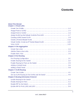 3
3 -
 4
4 -
 5
5 -
 6
6 -
 7
7 -
8
-
9
-
10
-
11
-
12
-
13
-
14
-
15
-
16
-
17
-
18
-
19
-
20
-
21
-
22
-
23
-
24
-
25
-
26
-
27
-
28
-
29
-
30
-
31
-
32
-
33
-
34
-
35
-
36
-
37
-
38
-
39
-
40
-
41
-
42
-
43
-
44
-
45
-
46
-
47
-
48
-
49
-
50
-
51
-
52
-
53
-
54
-
55
-
56
-
57
-
58
-
59
-
60
-
61
-
62
-
63
-
64
-
65
-
66
-
67
-
68
-
69
-
70
-
71
-
72
-
73
-
74
-
75
-
76
-
77
-
78
-
79
-
80
-
81
-
82
-
83
-
84
-
85
-
86
-
87
-
88
-
89
-
90
-
91
-
92
-
93
-
94
-
95
-
96
-
97
-
98
-
99
-
100
-
101
-
102
-
103
-
104
-
105
-
106
-
107
-
108
-
109
-
110
-
111
-
112
-
113
-
114
-
115
-
116
-
117
-
118
-
119
-
120
-
121
-
122
-
123
-
124
-
125
-
126
-
127
-
128
-
129
-
130
-
131
-
132
-
133
-
134
-
135
-
136
-
137
-
138
-
139
-
140
-
141
-
142
-
143
-
144
-
145
-
146
-
147
-
148
-
149
-
150
-
151
-
152
-
153
-
154
-
155
-
156
-
157
-
158
-
159
-
160
-
161
-
162
-
163
-
164
-
165
-
166
-
167
-
168
-
169
-
170
-
171
-
172
-
173
-
174
-
175
-
176
-
177
-
178
-
179
-
180
-
181
-
182
-
183
-
184
-
185
-
186
-
187
-
188
-
189
-
190
-
191
-
192
-
193
-
194
-
195
-
196
-
197
-
198
-
199
-
200
-
201
-
202
-
203
-
204
-
205
-
206
-
207
-
208
-
209
-
210
-
211
-
212
-
213
-
214
-
215
-
216
-
217
-
218
-
219
-
220
-
221
-
222
-
223
-
224
-
225
-
226
-
227
-
228
-
229
-
230
-
231
-
232
-
233
-
234
-
235
-
236
-
237
-
238
-
239
-
240
-
241
-
242
-
243
-
244
-
245
-
246
-
247
-
248
-
249
-
250
-
251
-
252
-
253
-
254
-
255
-
256
-
257
-
258
-
259
-
260
-
261
-
262
-
263
-
264
-
265
-
266
-
267
-
268
-
269
-
270
-
271
-
272
-
273
-
274
-
275
-
276
-
277
-
278
-
279
-
280
-
281
-
282
-
283
-
284
-
285
-
286
-
287
-
288
-
289
-
290
-
291
-
292
-
293
-
294
-
295
-
296
-
297
-
298
-
299
-
300
-
301
-
302
-
303
-
304
-
305
-
306
-
307
-
308
-
309
-
310
-
311
-
312
-
313
-
314
-
315
-
316
-
317
-
318
-
319
-
320
-
321
-
322
-
323
-
324
-
325
-
326
-
327
-
328
-
329
-
330
-
331
-
332
-
333
-
334
-
335
-
336
-
337
-
338
-
339
-
340
-
341
-
342
-
343
-
344
-
345
-
346
-
347
-
348
-
349
-
350
-
351
-
352
-
353
-
354
-
355
-
356
-
357
-
358
-
359
-
360
-
361
-
362
-
363
-
364
-
365
-
366
-
367
-
368
-
369
-
370
-
371
-
372
-
373
-
374
-
375
-
376
-
377
-
378
-
379
-
380
-
381
-
382
-
383
-
384
-
385
-
386
-
387
-
388
-
389
-
390
-
391
-
392
-
393
-
394
-
395
-
396
-
397
-
398
-
399
-
400
-
401
-
402
-
403
-
404
-
405
-
406
-
407
-
408
-
409
-
410
-
411
-
412
-
413
-
414
-
415
-
416
-
417
-
418
-
419
-
420
-
421
-
422
-
423
-
424
-
425
-
426
-
427
-
428
-
429
-
430
-
431
-
432
-
433
-
434
-
435
-
436
-
437
-
438
-
439
-
440
-
441
-
442
-
443
-
444
-
445
-
446
-
447
-
448
-
449
-
450
-
451
-
452
-
453
-
454
-
455
-
456
-
457
-
458
-
459
-
460
-
461
-
462
-
463
-
464
-
465
-
466
-
467
-
468
-
469
-
470
-
471
-
472
-
473
-
474
-
475
-
476
-
477
-
478
-
479
-
480
-
481
-
482
-
483
-
484
-
485
-
486
-
487
-
488
-
489
-
490
-
491
-
492
-
493
-
494
-
495
-
496
-
497
-
498
-
499
-
500
-
501
-
502
-
503
-
504
-
505
-
506
-
507
-
508
-
509
-
510
-
511
-
512
-
513
-
514
-
515
-
516
-
517
-
518
-
519
-
520
-
521
-
522
-
523
-
524
-
525
-
526
-
527
-
528
-
529
-
530
-
531
-
532
-
533
-
534
-
535
-
536
-
537
-
538
-
539
-
540
-
541
-
542
-
543
-
544
-
545
-
546
-
547
-
548
-
549
-
550
-
551
-
552
-
553
-
554
-
555
-
556
-
557
-
558
-
559
-
560
-
561
-
562
 |
 |
202-10515-03
June 2010
v1.0
NETGEAR
, Inc.
350 East Plumeria Drive
San Jose, CA 95134
ProSafe 7000 Managed
Switch Software
Administration Manual,
Release 8.0.3