Onkyo TX-DS838 Owner Manual - Page 12
disconnect
 |
View all Onkyo TX-DS838 manuals
Add to My Manuals
Save this manual to your list of manuals |
Page 12 highlights
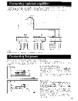
Connecting audio equipment Refer to the instruction manual of each component when making connections. On each pair of connectors, the lower connector (red and marked R) corresponds to the right channel and the upper connector (white and marked L) to the left channel. Turntable 0 PHONO OUT ,7n no q,c+ Fir • To wall outlet CAUTION: Do not plug in the power cord until all connections have been made. C O A CD player, MD recorder, DAT deck or other component equipped with an optical or coaxial connector can be connected to the TX-DS838. Even when one of these connectors are being used, do not disconnect the analog connection cable. OUTPUT CD player uT LINE IN I TI LINE OUT 1 =M.. 00 Tape deck LINE IN y iA LINE OUT =I= ooe ee Tape deck Remote control connections Cassette tape decks and a compact disc player that are equipped with an Onkyo RI connector can be operated using the remote control included with this unit. To enable remote control operation of other components, connect the remote control cable as shown at the right. Connect the remote control cable to the black connector with the RI mark, never connect it to the green or gray connector with the ITR>X mark. NOTE: • To enable proper remote control operation, both the RI cables and the audio cables must be connected to the units. • This unit's remote control cannot be used to control Onkyo turntables. • An RI remote control cable equipped with 1/8" (3.5 mm) mini jacks is included with any other component installed with an RI connector. AC outlet connections [1] The power to components connected to the SWITCHED outlet is turned on and off using the power buttons on the front panel and remote control. NOTF: • The shape, number and total capacity of the AC outlets may differ according to the model and the area where the unit is purchased. Be careful that other components connected to this unit do not exceed the capacity that is printed on the rear panel above the AC outlets. 12 B RI I I I I 1 I I
-
 1
1 -
2
-
3
-
4
-
5
-
6
-
 7
7 -
 8
8 -
 9
9 -
 10
10 -
 11
11 -
 12
12 -
 13
13 -
 14
14 -
 15
15 -
 16
16 -
 17
17 -
18
-
19
-
20
-
21
-
22
-
23
-
24
-
25
-
26
-
27
-
28
-
29
-
30
-
31
-
32
-
33
-
34
-
35
-
36
-
37
-
38
-
39
-
40
-
41
-
42
-
43
-
44
-
45
-
46
-
47
-
48
-
49
-
50
 |
 |
