Panasonic TH50PX500U TH42PX500U User Guide - Page 14
PC Input Terminals Connection, Notes, Signal Names for D-sub 15P Connector, Model, TH-42PX500U, Aspect - th 50px500u
 |
View all Panasonic TH50PX500U manuals
Add to My Manuals
Save this manual to your list of manuals |
Page 14 highlights
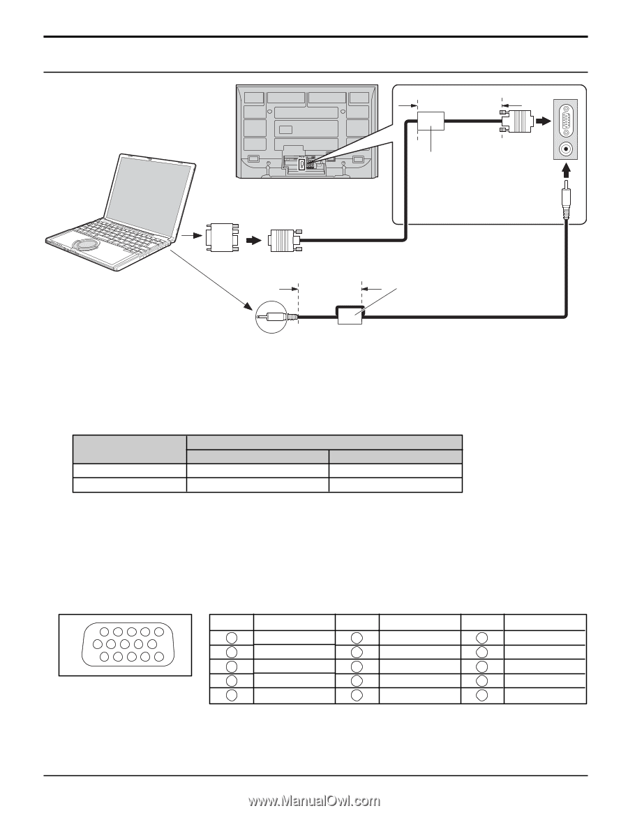
Connection PC Input Terminals Connection COMPUTER AV IN R L AUDIO IN Less than 10cm (4") D-sub 15p Ferrite core (Small size gray color) Conversion adapter (if necessary) RGB PC cable Stereo plug Less than 10cm (4") Ferrite core (Small size white color) Audio Connect a cable which matches the audio output terminal on the computer. Notes: (1) Computer signals which can be input are those with a horizontal scanning frequency of 15 to 110 kHz and vertical scanning frequency of 48 to 120 Hz. (However, the image will not be displayed properly if the signals exceed 1,200 lines.) (2) The maximum resolution: Model TH-42PX500U TH-50PX500U 4:3 768 × 768 1,024 × 768 Aspect 16:9 1,024 × 768 1,366 × 768 If the display resolution exceeds these maximums, it may not be possible to show fine detail with sufficient clarity. (3) Some PC models cannot be connected to the set. (4) There is no need to use an adapter for computers with IBM PC/AT compatible D-sub 15P terminal. (5) The computer shown in the illustration is for example purposes only. (6) Additional equipment and cables shown are not supplied with this set. Signal Names for D-sub 15P Connector 11 12 13 14 15 6 7 8 9 10 12345 Pin Layout for PC Input Terminal Pin No. Signal Name Pin No. Signal Name Pin No. Signal Name 1 R 6 GND (Ground) 11 NC (not connected) 2 G 7 GND (Ground) 12 NC 3 B 8 GND (Ground) 13 HD/SYNC 4 NC (not connected) 9 NC (not connected) 14 VD 5 GND (Ground) 10 GND (Ground) 15 NC 14
-
 1
1 -
2
-
3
-
4
-
5
-
6
-
7
-
8
-
 9
9 -
 10
10 -
 11
11 -
 12
12 -
 13
13 -
 14
14 -
 15
15 -
 16
16 -
 17
17 -
 18
18 -
 19
19 -
20
-
21
-
22
-
23
-
24
-
25
-
26
-
27
-
28
-
29
-
30
-
31
-
32
-
33
-
34
-
35
-
36
-
37
-
38
-
39
-
40
-
41
-
42
-
43
-
44
-
45
-
46
-
47
-
48
-
49
-
50
-
51
-
52
-
53
-
54
-
55
-
56
-
57
-
58
-
59
-
60
-
61
-
62
-
63
-
64
-
65
-
66
-
67
-
68
-
69
-
70
-
71
-
72
-
73
-
74
-
75
-
76
-
77
-
78
-
79
-
80
-
81
-
82
-
83
-
84
-
85
-
86
-
87
-
88
-
89
-
90
-
91
-
92
-
93
-
94
-
95
-
96
-
97
-
98
-
99
-
100
-
101
-
102
-
103
-
104
-
105
-
106
-
107
-
108
-
109
-
110
-
111
-
112
-
113
-
114
-
115
-
116
-
117
-
118
-
119
-
120
-
121
-
122
-
123
-
124
-
125
-
126
-
127
-
128
-
129
-
130
-
131
-
132
-
133
-
134
-
135
-
136
-
137
-
138
-
139
-
140
-
141
-
142
-
143
-
144
-
145
-
146
-
147
-
148
-
149
-
150
-
151
-
152
-
153
-
154
-
155
-
156
-
157
-
158
-
159
-
160
-
161
-
162
-
163
-
164
-
165
-
166
-
167
-
168
-
169
-
170
-
171
-
172
-
173
-
174
-
175
-
176
-
177
-
178
-
179
-
180
-
181
-
182
-
183
-
184
-
185
-
186
-
187
-
188
-
189
-
190
-
191
-
192
-
193
 |
 |