Samsung CLP 600N User Manual (ENGLISH) - Page 69
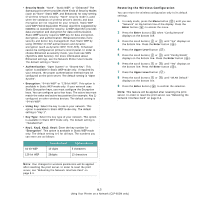
into a network LAN connection., network port on the printer and the other end of the cable
 |
UPC - 635753703016
View all Samsung CLP 600N manuals
Add to My Manuals
Save this manual to your list of manuals |
Page 69 highlights
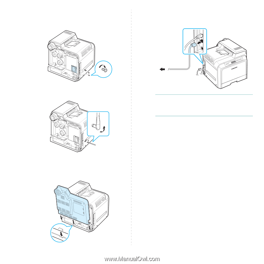
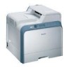
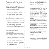
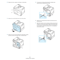
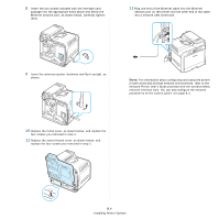
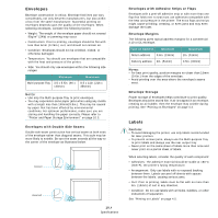
8 Insert the two screws included with the interface card package into the appropriate holes above and below the Ethernet network port, as shown below. Carefully tighten them. 12 Plug one end of the Ethernet cable into the Ethernet network port on the printer and the other end of the cable into a network LAN connection. 9 Insert the antenna counter clockwise and flip it upright, as shown. NOTE: For information about configuring and using the printer in both wired and wireless network environments, refer to the Network Printer User's Guide provided with the wired/wireless network interface card. You can also configure the network parameters on the control panel; see page 8.4. 10 Replace the metal cover, as shown below, and replace the four screws you removed in step 4. 11 Replace the control board cover, as shown below, and replace the four screws you removed in step 2. 9.4 Installing Printer Options
-
 1
1 -
2
-
3
-
4
-
5
-
6
-
7
-
8
-
9
-
10
-
11
-
12
-
13
-
14
-
15
-
16
-
17
-
18
-
19
-
20
-
21
-
22
-
23
-
24
-
25
-
26
-
27
-
28
-
29
-
30
-
31
-
32
-
33
-
34
-
35
-
36
-
37
-
38
-
39
-
40
-
41
-
42
-
43
-
44
-
45
-
46
-
47
-
48
-
49
-
50
-
51
-
52
-
53
-
54
-
55
-
56
-
57
-
58
-
59
-
60
-
61
-
62
-
63
-
 64
64 -
 65
65 -
 66
66 -
 67
67 -
 68
68 -
 69
69 -
 70
70 -
 71
71 -
 72
72 -
 73
73 -
 74
74 -
75
-
76
-
77
-
78
-
79
-
80
-
81
-
82
-
83
-
84
-
85
-
86
-
87
-
88
-
89
-
90
-
91
-
92
-
93
-
94
-
95
-
96
-
97
-
98
-
99
-
100
-
101
-
102
-
103
-
104
-
105
-
106
-
107
-
108
-
109
-
110
-
111
-
112
-
113
-
114
-
115
 |
 |