Sony DCR-TRV10 Service Manual
Sony DCR-TRV10 - Digital Video Camera Recorder Manual
 |
View all Sony DCR-TRV10 manuals
Add to My Manuals
Save this manual to your list of manuals |
Sony DCR-TRV10 manual content summary:
- Sony DCR-TRV10 | Service Manual - Page 1
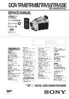
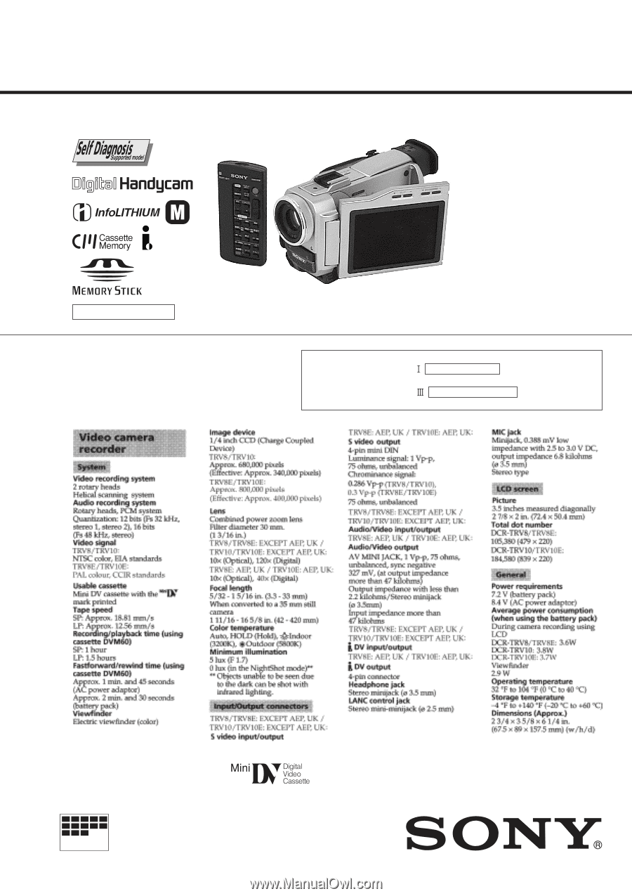
TRV10/TRV10E DCR-TRV8/TRV10: NTSC model DCR-TRV8E/TRV10E: PAL model For MECHANISM ADJUSTMENTS, refer to the "DV MECHANICAL ADJUSTMENT MANUAL D MECHANISM " (original: 9-973-81511, supplement: 9-973-815-81) and "DV MECHANICAL ADJUSTMENT MANUAL D200 MECHANISM " (original: 9-973981-11). SPECIFICATIONS - Sony DCR-TRV10 | Service Manual - Page 2
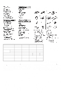
following accessories are supplied with your camcorder. • DIFFERENCE TABLE Model DCR-TRV8 Color System NTSC Remote Commander RMT-808 Lens Memory Stick Optical Digital 10 × 120 × - DCR-TRV8E PAL RMT-808 RMT-809 * 10 × 120 ×, 40 × * - DCR-TRV10 NTSC RMT-811 10 × 120 × g DCR-TRV10E PAL RMT - Sony DCR-TRV10 | Service Manual - Page 3
DV tape - DV synchro-editing (DCR-TRV10E only 1-18 Audio dubbing 1-18 Superimposing a title 1-19 Making your own titles 1-20 Labeling a cassette 1-20 Customizing Your Camcorder 1-21 Changing the MENU settings 1-21 Resetting the date and time 1-22 Memory Stick Operations 1-23 Using a memory - Sony DCR-TRV10 | Service Manual - Page 4
(VC-CK CONNECT) PRINTED WIRING BOARD 4-47 • VC-217 (FOCUS/ZOOM MOTOR DRIVE, CAMERA, BLOCKING COMPRESS, VIDEO INTERFACE, DV PROCESS, REC/PB HEAD AMP, VIDEO IN/OUT, MECHANISM 5-1. CAMERA SECTION ADJUSTMENT 5-4 1-1. PREPARATIONS BEFORE ADJUSTMENT (CAMERA SECTION 5-4 1-1-1. List of Service Tools - Sony DCR-TRV10 | Service Manual - Page 5
adjustment remote commander 5-55 2. Precautions upon using the adjustment remote commander 5-55 4-2. DATA PROCESS 5-56 4-3. SERVICE MODE 5-57 1. Setting the Test Mode 5-57 2. Emergence Memory Address 5-57 2-1. EMG Code (Emergency Code 5-57 2-2. MSW Code 5-58 3. Bit value discrimination 5-59 - Sony DCR-TRV10 | Service Manual - Page 6
is supplied to the battery terminal using the regulated power supply (8.4 V), the power is shut off so that the unit cannot operate. This following two methods are available to prevent this. Take note of which to use during repairs. Method 1. Connect the servicing remote commander RM-95 (J-6082 - Sony DCR-TRV10 | Service Manual - Page 7
display and service mode display. indicates the "repaired by:", "block" in which the problem occurred, Details of the self-diagnosis functions are provided in the Instruction and "detailed code" of the problem. manual. Viewfinder or LCD screen LCD window C : 3 1 : 1 1 C : 3 1 : 11 Blinks - Sony DCR-TRV10 | Service Manual - Page 8
T reel fault. Remove the battery or power cable, connect, and perform operations from the beginning. 2 3 S reel fault. Remove the battery or power cable, connect, and perform operations from the beginning. 2 4 T reel fault. Remove the battery or power cable, connect, and perform operations from - Sony DCR-TRV10 | Service Manual - Page 9
1. GENERAL DCR-TRV8/TRV8E/TRV10/TRV10E This section is extracted from instruction manual. (DCR-TRV8E/TRV10E model) 1-1 - Sony DCR-TRV10 | Service Manual - Page 10
1-2 - Sony DCR-TRV10 | Service Manual - Page 11
1-3 - Sony DCR-TRV10 | Service Manual - Page 12
1-4 - Sony DCR-TRV10 | Service Manual - Page 13
1-5 - Sony DCR-TRV10 | Service Manual - Page 14
1-6 - Sony DCR-TRV10 | Service Manual - Page 15
1-7 - Sony DCR-TRV10 | Service Manual - Page 16
1-8 - Sony DCR-TRV10 | Service Manual - Page 17
1-9 - Sony DCR-TRV10 | Service Manual - Page 18
1-10 - Sony DCR-TRV10 | Service Manual - Page 19
1-11 - Sony DCR-TRV10 | Service Manual - Page 20
1-12 - Sony DCR-TRV10 | Service Manual - Page 21
1-13 - Sony DCR-TRV10 | Service Manual - Page 22
1-14 - Sony DCR-TRV10 | Service Manual - Page 23
1-15 - Sony DCR-TRV10 | Service Manual - Page 24
1-16 - Sony DCR-TRV10 | Service Manual - Page 25
1-17 - Sony DCR-TRV10 | Service Manual - Page 26
1-18 - Sony DCR-TRV10 | Service Manual - Page 27
1-19 - Sony DCR-TRV10 | Service Manual - Page 28
1-20 - Sony DCR-TRV10 | Service Manual - Page 29
1-21 - Sony DCR-TRV10 | Service Manual - Page 30
1-22 - Sony DCR-TRV10 | Service Manual - Page 31
1-23 - Sony DCR-TRV10 | Service Manual - Page 32
1-24 - Sony DCR-TRV10 | Service Manual - Page 33
1-25 - Sony DCR-TRV10 | Service Manual - Page 34
1-26 - Sony DCR-TRV10 | Service Manual - Page 35
1-27 - Sony DCR-TRV10 | Service Manual - Page 36
1-28 - Sony DCR-TRV10 | Service Manual - Page 37
1-29 - Sony DCR-TRV10 | Service Manual - Page 38
1-30 - Sony DCR-TRV10 | Service Manual - Page 39
1-31 - Sony DCR-TRV10 | Service Manual - Page 40
1-32 - Sony DCR-TRV10 | Service Manual - Page 41
1-33 - Sony DCR-TRV10 | Service Manual - Page 42
1-34 - Sony DCR-TRV10 | Service Manual - Page 43
1-35 - Sony DCR-TRV10 | Service Manual - Page 44
1-36 - Sony DCR-TRV10 | Service Manual - Page 45
1-37E - Sony DCR-TRV10 | Service Manual - Page 46
-TRV8/TRV8E/TRV10/TRV10E SECTION 2 DISASSEMBLY The following flow chart shows the disassembly procedure. DCR-TRV8/8E/10/10E 2-2. Front panel assembly 2-3. Cabinet (L), BT panel assembly 2-4.EVF 2-1. LCD panel (PD-110 board, invertor trans unit) 2-11. CK-84 board, Speaker 2- - Sony DCR-TRV10 | Service Manual - Page 47
2-2. FRONT PANEL ASSEMBLY 9 Tapping screw (M1.7 × 3.5) !º SE-94board CN7307 5P !¢ Two tapping screws (M1.7 × 3.5) 2 Top cabinet assembly (MA-358 board) 1 Screw (M1.7) lock ace !¡ Tapping screw (M1.7 × 3.5) !∞ Microphone retainer assembly !™ MA-358 board !£ Connector !§ Microphone unit - Sony DCR-TRV10 | Service Manual - Page 48
2-4. EVF 1 Screw (M1.7 × 2.5) 2 Two screws (M1.7 × 6) B tight 6 Tilt up the EVF. 8 Tilt down the EVF. 5 Two tapping screws (M1.7 × 6) 9 EVF assembly (Remove the assembly while holding it upward.) 4 Flexible retainer sheet 7 Screw (M1.7) lock ace 3 FP-87 flexible board CN5101 27P (DD-123 board) - Sony DCR-TRV10 | Service Manual - Page 49
2-6. DD-123 BOARD, VC-217 BOARD 4 FP-92 flexible board 3 DD-123 board 6 Flexible board (from drum motor) CN2501 (VC-217 board) 5 FP-85 flexible board 2 Screw (M1.7 × 2.5) CN1810 (VC-217 board) CN2507 (VC-217 board) 7 FP-586 flexible board CN2502 (VC-217 board) 1 Connector CN3201 3P (DD-123 - Sony DCR-TRV10 | Service Manual - Page 50
CS flame assembly 1 Remove it from the external connector (hot shoe). !¢ FP-85 flexible board !£ Screw (M1.7 × 2.5) 9 FP-84 flexible board (TRV10/TRV10E only) CN62 (FP-85 flexible board) 2-9. LENS, OUTER CONNECTOR (HOT SHOE), JK-170 BOARD Note for installation When installing the lens and the lens - Sony DCR-TRV10 | Service Manual - Page 51
power button on the cabinet (L) side. Area A 3 Two tapping screws 4 Control switch block (PS-4550) (M1.7 × 3.5) 1 Screw (M1.7 × 2.5) 2 Memory stick assembly NOTE: 1 and 2 are only in the TRV10/TRV10E START/STOP MODE switch (S8613) and the MANUAL FOCUS switch (S8614) with their respective knobs. - Sony DCR-TRV10 | Service Manual - Page 52
2-12.LCD, CONTROL SWITCH BLOCK 3 Slide the panel lock knob backward and open the LCD panel. 8 LCD assembly 6 FP-91 flexible board CN8606 6P (CK-84 board) 1 Three tapping screws (M1.7 × 3.5) 7 Two screws (M1.7) lock ace 2 Control switch block (CF-4550) CN8605 6P (CK-84 board) 5 Harness (PC-112) - Sony DCR-TRV10 | Service Manual - Page 53
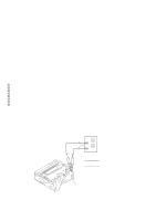
jig (J-6082-388-A) VC-217 board Base Mechanism deck EVF Cabinet (R) assembly and LCD Extension cable (J-6082-395-A) DD-123 board DC IN (8.4V) BT panel assembly AC adapter (AC-L10 and AC-VQ800,etc.) AC IN (Support the VC-217 board, lens block, and front panel assembly with a base or the - Sony DCR-TRV10 | Service Manual - Page 54
(MIC AMP, SIRCS IN) DD-123 (DC/DC CONVERTER) PD-110 RGB DECODER, LCD, TIMING GENERATOR VC-217 FOCUS/ZOOM MOTOR DRIVE, CAMERA, BLOCKING COMPRESS, VIDEO INTERFACE, DV PROCESS, REC/PB HEAD AMP, VIDEO IN/OUT, MECHANISM CONTROL, SERVO, HI CONTROL, AUDIO INVERTER TRANSFORMER UNIT SE-94 (MF DIAL) 2-9 - Sony DCR-TRV10 | Service Manual - Page 55
CONTROL SWITCH BLOCK (CF4550) FP-83 (CCD IMAGER) CONTROL SWITCH BLOCK (PS4550) FP-87 FP-82 FP-90 (BRT, VOL CONTROL) FP-91 FP-84 (TRV10/10E) FP-85 FP-586 (From LOADING MOTOR) (From DRUM MOTOR) LCD902 (included in FP-88) FP-242 (From LS CHASSIS) (From - Sony DCR-TRV10 | Service Manual - Page 56
SECTION 3 BLOCK DIAGRAMS 3-1. OVERALL BLOCK DIAGRAM (TRV8/TRV8E) DCR-TRV8/TRV8E/TRV10/TRV10E 3-1 3-2 3-3 3-4 - Sony DCR-TRV10 | Service Manual - Page 57
DCR-TRV8/TRV8E/TRV10/TRV10E 3-2. OVERALL BLOCK DIAGRAM (TRV10/TRV10E) 3-5 3-6 3-7 3-8 - Sony DCR-TRV10 | Service Manual - Page 58
3-3. POWER BLOCK DIAGRAM DCR-TRV8/TRV8E/TRV10/TRV10E 3-9 3-10 3-11 3-12E - Sony DCR-TRV10 | Service Manual - Page 59
DCR-TRV8/TRV8E/TRV10/TRV10E characteristics External dimensions (mm) (+,-) B LINE. * • C : adjustment for repair. * • Circled numbers refer to waveforms. * ground when camera shoots color bar of VOM used.) * 1. Connection Pattern box 1.5m Front side BA Fig. a (Video output terminal output waveform) - Sony DCR-TRV10 | Service Manual - Page 60
TRV8E/TRV10/TRV10E FP-83 (CCD IMAGER) PRINTED WIRING BOARD - Ref. No. FP-83 Flexible Board; 10,000 Series - FP-83 FLEXIBLE BOARD 1 7 C IC001 14 8 Q001 C003 C002 R001 FP-83 BOARD C001 B-2 C002 B-2 C003 B-2 C004 A-1 CN001 A-2 CN002 B-1 IC001 C-1 L001 A-1 Q001 C-2 R001 B-2 FP-83 BOARD CAMERA - Sony DCR-TRV10 | Service Manual - Page 61
For schematic diagram • Refer to page 4-48 for printed wiring board. DCR-TRV8/TRV8E/TRV10/TRV10E FOCUS/ZOOM MOTOR DRIVE 4-9 4-10 4-11 VC-217 (1/11) - Sony DCR-TRV10 | Service Manual - Page 62
DCR-TRV8/TRV8E/TRV10/TRV10E VC-217 BOARD (2/11) CAMERA REC 1 IC203 @§,@¶ For schematic diagram • Refer to page 4-48 for printed wiring board. H 2 IC203 2-!¡ 1.0Vp-p 56nsec 3.0Vp-p 3 IC202 5 CAMERA REC/PB 36.0MHz 3.2Vp-p 4 IC202 !™ CAMERA REC/PB 18.0MHz 3.2Vp-p 5 IC206 $º (X202) CAMERA - Sony DCR-TRV10 | Service Manual - Page 63
For schematic diagram • Refer to page 4-48 for printed wiring board. • This page is TRV10/TRV10E only. DCR-TRV8/TRV8E/TRV10/TRV10E VC-217 BOARD (3/11) 6 IC750 &¶ 6.86MHz 7 IC758 !£ 2.8Vp-p 20MHz 1.6Vp-p 4-15 4-16 4-17 BLOCKING COMPRESS VC-217 (3/11) - Sony DCR-TRV10 | Service Manual - Page 64
DCR-TRV8/TRV8E/TRV10/TRV10E VC-217 BOARD (4/11) CAMERA REC/PB 8 Q1500 E For schematic diagram • Refer to page 4-48 for printed wiring board. H 9 Q1501 E 0.12Vp-p 0.22Vp-p H !º Q1502 E H !¡ Q1503 E 0.28Vp-p H !™ Q1504 E 0.34Vp-p H !£ IC1502 8 0.45Vp-p 13.5MHz 3.0Vp-p VIDEO INTERFACE VC- - Sony DCR-TRV10 | Service Manual - Page 65
For schematic diagram • Refer to page 4-48 for printed wiring board. DCR-TRV8/TRV8E/TRV10/TRV10E VC-217 BOARD (5/11) CAMERA REC/PB !¢ IC1600 !¢ (X1600) 24.58MHz 1.8Vp-p DCR-TRV8/TRV8E/TRV10/TRV10E 4-21 4-22 4-23 DV PROCESS VC-217 (5/11) - Sony DCR-TRV10 | Service Manual - Page 66
DCR-TRV8/TRV8E/TRV10/TRV10E VC-217 BOARD (6/11) !∞ IC1816 1267 CAMERA REC For schematic diagram • Refer to page 4-48 for printed wiring board. 6.8msec 3.5Vp-p !§ IC1816 @¶ PB 6.8msec 0.3Vp-p !¶ IC1900 !¡ CAMERA REC 25nsec 2.2Vp-p REC/PB HEAD AMP VC-217 (6/11) 4-25 4-26 4-27 4-28 - Sony DCR-TRV10 | Service Manual - Page 67
printed wiring board. 4-29 4-30 DCR-TRV8/TRV8E/TRV10/TRV10E VC-217 BOARD (7/11) CAMERA REC/PB !• IC1200 @∞ LINE REC (NTSC) @£ IC1402 @∞ 0.44Vp-p H H !ª IC1200 #£ LINE REC (NTSC) @¢ IC1402 @ª 0.45Vp-p 0.37Vp-p H H @º IC1200 #¢ LINE REC (NTSC) @∞ IC1402 7 0.34Vp-p H @¡ IC1200 $¢ LINE - Sony DCR-TRV10 | Service Manual - Page 68
/TRV10/TRV10E FP-91 (TOP/END SENSOR), FP-92 (TAPE LED), FP-242 (S/T REEL SENSOR) PRINTED WIRING BOARDS - Ref. No. FP-91, 92, 242 Flexible Board; 10,000 Series - FP-91 FLEXIBLE FP-92 FLEXIBLE BOARD BOARD CN902 10 1 1 S902 MODE SWITCH 51 1 18 CN903 Q901 TAPE TOP VC-217 BOARD (8/11) CAMERA - Sony DCR-TRV10 | Service Manual - Page 69
For schematic diagram • Refer to page 4-48 for printed wiring board. 4-37 4-38 4-39 DCR-TRV8/TRV8E/TRV10/TRV10E VC-217 BOARD (9/11) CAMERA REC/PB @ª IC2503 4 #∞ IC2503 ^º 6.7msec 2.6Vp-p 1.1msec 2.7Vp-p 900kHz #º IC2503 #§ IC2503 ^£ 1.1msec 0.1Vp-p 1.1msec 0.23Vp-p 900kHz #¡ IC2503 - Sony DCR-TRV10 | Service Manual - Page 70
DCR-TRV8/TRV8E/TRV10/TRV10E VC-217 BOARD (10/11) CAMERA REC/PB $º IC2204 $º (X2200) For schematic diagram • Refer to page 4-48 for printed wiring board. 20.0MHz 2.8Vp-p $¡ IC2204 %£ (X2201, C2232) 32.767kHz 3.0Vp-p HI CONTROL VC-217 (10/11) 4-41 4-42 4-43 4-44 - Sony DCR-TRV10 | Service Manual - Page 71
For schematic diagram ¥ Refer to page 4-48 for printed wiring board. 4-45 DCR-TRV8/TRV8E/TRV10/TRV10E FP-82 (VC-CK CONNECT) PRINTED WIRING BOARD - Ref. No. FP-82 Flexible Board; 10,000 Series - FP-82 BOARD CN41 A-6 CN42 A-1 4-46 For printed wiring boards • This board is - Sony DCR-TRV10 | Service Manual - Page 72
DCR-TRV8/TRV8E/TRV10/TRV10E VC-217 BOARD (SIDE A) C205 D-2 C207 D-3 C212 C-2 C214 D-2 C215 C-2 C217 C-2 C218 C-2 C220 C-2 E-5 R2929 E-4 VC-217 (FOCUS/ZOOM MOTOR DRIVE, CAMERA, BLOCKING COMPRESS, VIDEO INTERFACE, DV PROCESS, REC/PB HEAD AMP, VIDEO IN/OUT, MECHANISM CONTROL, SERVO, HI CONTROL, AUDIO - Sony DCR-TRV10 | Service Manual - Page 73
VC-217 (FOCUS/ZOOM MOTOR DRIVE, CAMERA, BLOCKING COMPRESS, VIDEO INTERFACE, DV PROCESS, REC/PB HEAD AMP, VIDEO IN/OUT, MECHANISM CONTROL, SERVO, HI CONTROL, AUDIO) PRINTED WIRING BOARD - Ref. No. VC-217 Board; 10,000 Series - 4-51 4-52 DCR-TRV8/TRV8E/TRV10/TRV10E VC-217 BOARD (SIDE B) C202 C-15 - Sony DCR-TRV10 | Service Manual - Page 74
DCR-TRV8/TRV8E/TRV10/TRV10E R100 CK-84 ( S8611 E-7 S8612 D-4 S8613 C-7 S8614 A-11 S8615 B-2 PLAY INDEX MEMORY DELETE TRV10/TRV10E MODEL (RESET) FADER BACK LIGHT SELF TIMER END SEARCH DISPLAY 1-673-619 4-55 DIGITAL EFFECT TITLE MENU START/STOP MODE 5 SEC ANTI GRAND SHOOTING FOCUS AUTO - Sony DCR-TRV10 | Service Manual - Page 75
4-57 4-58 CK-84 BOARD 1 IC7501 $¡ PB 0.5Vp-p H 1 IC7501 $¡ LINE REC (NTSC) 0.5Vp-p H 2 IC7501 @™ (NTSC) LINE REC/PB (IR ON) 82nsec 0.8Vp-p DCR-TRV8/TRV8E/TRV10/TRV10E 4-59 / FUNCTION SWITCH, IR CONTROL DIAL, PANEL REV/CLOSE CK-84 CF4550/FP-91 - Sony DCR-TRV10 | Service Manual - Page 76
DCR-TRV8/TRV8E/TRV10/TRV10E JK-170 (AV IN/OUT) PRINTED WIRING BOARD - Ref. No. JK-170 Board; 1,000 Series - AV IN/OUT JK-170 4-61 S VIDEO EXCEPT AEP, UK MODEL AEP, UK MODEL DV IN/OUT DV OUT 4-62 JK-170 BOARD C400 C-3 C401 C-3 C450 C-3 C451 A-8 C453 B-9 C454 A-3 C455 A-3 C456 B-9 C457 C-3 - Sony DCR-TRV10 | Service Manual - Page 77
SIRCS IN) PRINTED WIRING BOARD - Ref. No. MA-358 Board; 10,000 Series - MIC (PLUG IN POWER) AUDIO/VIDEO 4-65 MA-358 BOARD C7300 E-3 C7301 B-3 C7302 E-2 C7305 D-2 C7306 B-2 C7307 D-2 C7308 B-2 C7309 D-2 -358 (MIC AMP, SIRCS IN) 4-66 4-67 DCR-TRV8/TRV8E/TRV10/TRV10E 4-68 MIC AMP, SIRCS IN MA-358 - Sony DCR-TRV10 | Service Manual - Page 78
DCR-TRV8/TRV8E/TRV10/TRV10E DCR-TRV8/TRV8E/TRV10/TRV10E SE-94 (MF DIAL), LB-60 (BACK LIGHT DRIVE GENERATOR INVERTER TRANSFORMER UNIT VC-217 FOCUS/ZOOM MOTOR DRIVE, CAMERA, BLOCKING COMPRESS, VIDEO INTERFACE, DV PROCESS, REC/PB HEAD AMP, VIDEO IN/OUT, MECHANISM CONTROL, SERVO, HI CONTROL, AUDIO SE - Sony DCR-TRV10 | Service Manual - Page 79
DCR-TRV8/TRV8E/TRV10/TRV10E LB-60 BOARD CAMERA REC/PB 1 IC5101 !∞ 12.0Vp-p H DCR-TRV8/TRV8E/TRV10/TRV10E BACK LIGHT DRIVE 4-73 4-74 LB-60 4-75 - Sony DCR-TRV10 | Service Manual - Page 80
DCR-TRV8/TRV8E/TRV10/TRV10E DCR-TRV8/TRV8E/TRV10/TRV10E FP-90 (BRT, VOL CONTROL), PD-110 (RGB • Chip parts Transistor C VC-217 FOCUS/ZOOM MOTOR DRIVE, CAMERA, BLOCKING COMPRESS, VIDEO INTERFACE, DV PROCESS, REC/PB HEAD AMP, VIDEO IN/OUT, MECHANISM CONTROL, SERVO, HI CONTROL, AUDIO INVERTER - Sony DCR-TRV10 | Service Manual - Page 81
4-79 4-80 DCR-TRV8/TRV8E/TRV10/TRV10E PD-110 BOARD (1/2) CAMERA REC/PB 1 IC5502 8 H 2 IC5502 9 0.3Vp-p H 3 IC5502 !º 0.22Vp-p H 4 IC5502 @º 0.14Vp-p 3.5Vp-p 2H 5 IC5502 @™ 3.5Vp-p 2H 6 IC5502 @¢ 4.0Vp-p 2H 7 IC5502 $¡ 1.6Vp-p 2H 4-81 / BRT, VOL CONTROL RGB - Sony DCR-TRV10 | Service Manual - Page 82
DCR-TRV8/TRV8E/TRV10/TRV10E PD-110 BOARD (2/2) CAMERA REC/PB 8 IC5601 @§ For schematic diagram ¥ Refer to page 4-77 for printed wiring board. 16.7MHz 9 IC5601 #¢ 3.0Vp-p 2.7Vp-p V !º IC5601 #¶ H !¡ IC5602 7 2.7Vp-p 6.8Vp-p 2H TIMING GENERATOR PD-110 (2/2) 4-82 4-83 4-84 - Sony DCR-TRV10 | Service Manual - Page 83
CN62 8 1 LASER LINK S72 D72 16 1-673-615- 11 CONTROL SWITCH BLOCK (PS4550) YE A0001 61 8 S2 START/STOP POWER S1 VTR PLAYER AEP, UK MODEL OFF EXCEPT AEP, UK MODEL CAMERA MEMORY TRV10/TRV10E MODEL 1-418-350- 11 16 S61 (EJECT) FP-87 FP-91 CONTROL SWITCH BLOCK (CF4550) FP-83 (CCD IMAGER - Sony DCR-TRV10 | Service Manual - Page 84
DCR-TRV8/TRV8E/TRV10/TRV10E DD-123 (COLOR EVF, DC/DC CONVERTER) PRINTED WIRING BOARD DECODER, LCD, TIMING GENERATOR VC-217 FOCUS/ZOOM MOTOR DRIVE, CAMERA, BLOCKING COMPRESS, VIDEO INTERFACE, DV PROCESS, REC/PB HEAD AMP, VIDEO IN/OUT, MECHANISM CONTROL, SERVO, HI CONTROL, AUDIO INVERTER TRANSFORMER - Sony DCR-TRV10 | Service Manual - Page 85
4-91 4-92 4-93 DCR-TRV8/TRV8E/TRV10/TRV10E DD-123 BOARD (1/2) CAMERA REC/PB 1 IC5001 8 7 IC5102 $¡ H 2 IC5001 9 0.28Vp-p 16.06MHz 3.6Vp-p 8 IC5102 !• 2.8Vp-p H 3 IC5001 !º 0.2Vp-p 17.0msec 9 IC5102 @º,@¡ 2.8Vp-p H 4 IC5001 @º 0.15Vp-p 127µsec !º IC5102 @™ 2H 5 IC5001 @™ 7Vp-p H - Sony DCR-TRV10 | Service Manual - Page 86
DCR-TRV8/TRV8E/TRV10/TRV10E DD-123 BOARD (2/2) CAMERA REC/PB !™ IC3200 $• For schematic diagram • Refer to page 4-89 for printed wiring board. 2.6msec !£ IC3200 $¶ 4.5Vp-p 2.6msec 4.5Vp-p DC/DC CONVERTER DD-123 (2/2) 4-95 4-96 4-97 4-98E - Sony DCR-TRV10 | Service Manual - Page 87
DCR-TRV8/TRV8E/TRV10/TRV10E SECTION 5 ADJUSTMENTS 1. Before starting adjustment EVR Data Re-writing Procedure When Replacing Board The data that is stored in the repair before starting repair) PC PC (Machine after a board is replaced) Save the EVR data to a personal computer. Download the - Sony DCR-TRV10 | Service Manual - Page 88
Adjustment Adjustment Section Color EVF blockLCD903 (LCD panel) Mechanism deck Lens device Initialization of B, C, D, E, F page data Camera Color EVF LCD Servo & RF Video IR Mechanism Initialization of C page data Initialization of D page data Initialization of B page data Initialization of - Sony DCR-TRV10 | Service Manual - Page 89
PD-110 board DD-123 board LB-60 board CK-84 board VC-217 board VC-217 board Initialization of B, C, D, E, F page data Camera Color EVF LCD Servo & RF Video IR Mechanism Initialization of C page data Initialization of D page data Initialization of B page data Initialization of E, F page data 36 MHz - Sony DCR-TRV10 | Service Manual - Page 90
ADJUSTMENT (CAMERA SECTION) 1-1-1. List of Service Tools • Oscilloscope • Regulated power supply • Color monitor • Digital voltmeter CPC-8 jig For adjusting the video section J-6082-388-A For adjusting the color viewfinder For adjusting the LCD block J-9 Extension cable (80P, 0.4mm) J-6082- - Sony DCR-TRV10 | Service Manual - Page 91
Connect the equipment for adjustments according to Fig. 5-1-2. 2) The front panel block (MA-358 board, focus ring, Audio/video " for the self-diagnosis data, and to "5-4.Service Mode" for the data on the history use.) Note 4: Setting the "Forced Camera Power ON" Mode 1) Select page: 0, address: - Sony DCR-TRV10 | Service Manual - Page 92
board CN3201 CN8610 Terminated at 75Ω Adjustment remote commander Viewfinder Must be connected when performing the video system, color EVF system or LCD system adjustments. Extension cable J-6082-395-A (80P 0.4mm) Battery terminal Must be connected when using the viewfinder. Fig. 5-1-3. 5-6 - Sony DCR-TRV10 | Service Manual - Page 93
POWER switch (PS4550 block CAMERA 2. NIGHT SHOT switch (Lens block OFF 3. DEMO MODE (Menu display OFF 4. DIGITAL MANUAL 12. PROGRAM AE (CF block AUTO 13. DIGITAL Video output terminal output waveform) V Enlargement Fig. b (TV monitor picture) Difference in level B A Adjust the camera - Sony DCR-TRV10 | Service Manual - Page 94
adjustments 3) Video system adjustments shown in the following table by manual input. Modifying Method: 1) Before changing the different model, the camcorder may not operate. 3) Data".) Address Initial value Remark NTSC PAL 00 to 0F 10 EE EE 37 38 00 00 Emergency memory address 39 00 00 3A - Sony DCR-TRV10 | Service Manual - Page 95
Address Initial value Remark NTSC PAL 41 00 00 Emergency memory address 42 00 00 43 00 00 44 03 03 APC adj. 74 Fixed data-1 75 (Initialized data) 76 77 Address Initial value Remark NTSC PAL 78 Fixed data-1 79 (Initialized data) 7A 7B 7C 7D 7E Fixed data-2 7F (Modified - Sony DCR-TRV10 | Service Manual - Page 96
NTSC PAL address shown in the following table by manual input. Modifying Method: 1) Before changing the different model, the camcorder may not operate. 3) the non-volatile memory. 4) Check that battery end mark on the LCD or viewfinder screen is flashing. 2) The power is shut off so that - Sony DCR-TRV10 | Service Manual - Page 97
the same model.) 3B 3C Fixed data-1 3D Fixed data-2 3E 3F Fixed data-1 40 Fixed data-2 *1: No mark: DCR-TRV10/TRV10E < >: DCR-TRV8/TRV8E Address Initial value Remark NTSC PAL 41 Fixed data-2 42 (Modified data, copy the data built in 43 the same model.) 44 45 Fixed data-1 46 - Sony DCR-TRV10 | Service Manual - Page 98
DCR-TRV10/TRV10E < >: DCR-TRV8/TRV8E Address Initial value Remark NTSC PAL 00 to FF Switch setting POWER MEMORY Initializing Method: 1) Select page address shown in the following tables by manual input. Processing before Modification of B the different model, the camcorder may not operate. 3) - Sony DCR-TRV10 | Service Manual - Page 99
3. B Page Table Note: Fixed data-1 : Initialized data. (Refer to "1. Initializing the B Page Data".) Fixed data-2 : Modified data. (Refer to "2. Modification of B Page Data".) Address Remark 00 Fixed data-2 (Modified data, copy the data built in the same model.) 01 Fixed data-1 02 ( - Sony DCR-TRV10 | Service Manual - Page 100
page data 2) Camera system adjustments address: 01, and set data: 2D (NTSC) or data: 2F (PAL) , and press the PAUSE button of address shown in the following table by manual input. Modifying Method: 1) Before changing the different model, the camcorder may not operate. non-volatile memory. 4) Check - Sony DCR-TRV10 | Service Manual - Page 101
. (Refer to "2. Modification of E, F Page Data".) Address Initial value NTSC PAL Remark 00 to 0F 10 Fixed data-1 11 (Initialized data) 12 Fixed data input 3F 7A 7A 40 Fixed data-2 Address Initial value Remark NTSC PAL 41 60 60 Angular velocity sensor sensitivity 42 60 60 adj. 43 - Sony DCR-TRV10 | Service Manual - Page 102
Address Initial value Remark NTSC PAL 77 Fixed data-1 78 (Initialized data) 79 7A 7B 7C Fixed (Initialized data) A0 A1 A2 A3 A4 A5 A6 A7 A8 A9 AA AB Address Initial value Remark NTSC PAL AC Fixed data-1 AD (Initialized data) AE AF B0 B1 B2 B3 B4 B5 B6 B7 B8 - Sony DCR-TRV10 | Service Manual - Page 103
data. (Refer to "1. Initializing the E, F Page Data".) Fixed data-2 : Modified data. (Refer to "2. Modification of E, F Page Data".) Address Initial value NTSC PAL Remark 00 Fixed data-2 01 Fixed data-1 02 (Initialized data) 03 04 05 06 07 08 Fixed data-2 09 (Modified data, copy the - Sony DCR-TRV10 | Service Manual - Page 104
Address Initial value Remark NTSC PAL 32 Fixed data-1 33 (Initialized data) 34 35 36 37 38 39 3A 73 73 AGC gain calibration adj. 3B 4B 4B 3C 7E 7E - Sony DCR-TRV10 | Service Manual - Page 105
SYSTEM ADJUSTMENTS Before perform the camera system adjustments, check that the specified value of "VIDEO SYSTEM ADJUSTMENT" are satisfied. 1. 36 MHz Origin Oscillation Adjustment (VC-217 board) Set the frequency of the clock for synchronization. If deviated, the synchronization will - Sony DCR-TRV10 | Service Manual - Page 106
auto focusing/manual focusing. Camcorder Camera table Regulated power supply 11.29 ± 0.01Vdc Output current more than 3.5A Red (+) Black (-) Yellow (SENS +) White (SENS -) Black (GND) Need not connected 3D, and check that the upper digit and lower digit of the data satisfies each specified value - Sony DCR-TRV10 | Service Manual - Page 107
In whichever case, the focus will be deviated during auto focusing/manual focusing. 5-1. Flange Back Adjustment(1) Subject Flange back adjustment chart Address 24 to 29, 36 to 3D, 5D Specified Value Upper digit: 0 to 9 Lower digit: 0 to 9 Switch setting: NIGHT SHOT OFF Adjusting method: 1) - Sony DCR-TRV10 | Service Manual - Page 108
) Measurement Point Check operation on TV monitor Measuring Instrument Specified Value Focused at the TELE end and WIDE end. Switch setting: 1) NIGHT SHOT OFF 2) DIGITAL ZOOM (Menu display OFF 3) STEADY SHOT (Menu display OFF Note: When the auto focus is ON, the lens can be checked if it is - Sony DCR-TRV10 | Service Manual - Page 109
segment of the system check tape (XH5-5 (NTSC), XH5-5P (PAL)). 2) Attach the optical axis frame chart (transparent ) on the monitor TV screen. Center of monoscope image and that that of optical axis frame must be agree. 3) Set to the camera - Sony DCR-TRV10 | Service Manual - Page 110
front of the lens) Measurement Point Video output terminal Measuring Instrument Oscilloscope and TV monitor Specified Value A=B, C=D, E=F Switch setting: 1) NIGHT SHOT OFF 2) DIGITAL ZOOM (Menu display OFF Setting method: 1) Adjust the zoom and the camera direction, and set to the specified - Sony DCR-TRV10 | Service Manual - Page 111
Video output terminal Measuring Instrument Vectorscope Adjustment Page F Adjustment Address 2E, 30, 44, 45 Specified Value All color luminance points should settle within each color reproduction frame. Note: NTSC model: DCR-TRV8/TRV10 PAL model: DCR-TRV8E/TRV10E to the memory. Processing - Sony DCR-TRV10 | Service Manual - Page 112
12. Auto White Balance & LV Standard Data Input Subject Clear chart (Color reproduction adjustment frame) Adjustment Page F Adjustment Address 20 to 23, 3E, 3F Note 1: This adjustment should be carried out upon completion of "Color Reproduction Adjustment". Note 2: Check that the data of page: - Sony DCR-TRV10 | Service Manual - Page 113
and 0.1 Measurement Point Video output terminal Measuring displayed on the angular velocity sensor of the repair parts. At this time, note down also to NTSC model D41' = 92 / S451 D42' = 108 / S450 PAL model D41' = 148 / S451 D42' = 128 / S450 5) Convert D41' and D42' into hexadecimal digits - Sony DCR-TRV10 | Service Manual - Page 114
The back light (fluorescent tube) is driven by a high voltage AC power supply. Therefore, do not touch the back light holder to avoid adjusting the viewfinder system are concentrated in CN2904 of the VC-217 board. Connect the Measuring Instruments via the CPC-8 jig (J-6082-388-A). The following - Sony DCR-TRV10 | Service Manual - Page 115
, and set data: 00. 3. Contrast Adjustment (DD-123 board) Set the level of the VIDEO signal for driving the LCD to the specified value. If deviated, the screen image will be blackish or saturated (whitish). Mode Camera Subject Measurement Point Arbitrary Pin 4 of CN2904 (EVF VG) on VC-217 board - Sony DCR-TRV10 | Service Manual - Page 116
Camera Digital voltmeter DCR-TRV10 DCR-TRV8 DCR-TRV10E DCR -TRV8E 71 72 8B 6A 99 5A 80 62 9A 59 5) Check that the EVF screen is not colored. If colored, change the data of page: D, address: 71 and 72 so that the EVF screen is not colored. Note: To write in the non-volatile memory - Sony DCR-TRV10 | Service Manual - Page 117
driven by a high voltage AC power supply. Therefore, do not touch are concentrated in CN2904 of the VC-217 board. Connect the Measuring Instruments via the CPC-8 jig (J-6082-388A Address 84 Specified Value f = 15734 ± 30Hz (NTSC) f = 15625 ± 30Hz (PAL) Adjusting method: 1) Select page: 0, address: - Sony DCR-TRV10 | Service Manual - Page 118
01, and set data: 00. 3. Bright Adjustment (PD-110 board) Set the level of the VIDEO signal for driving the LCD to the specified value. If deviated, the screen image will be blackish or saturated (whitish). Mode Camera Subject Measurement Point Arbitrary Pin 7 of CN2904 (PD VG) on VC-217 board - Sony DCR-TRV10 | Service Manual - Page 119
4. Contrast Adjustment (PD-110 board) Set the level of the VIDEO signal for driving the LCD to the specified value. If deviated, the screen image will be blackish or saturated (whitish). Mode Camera Subject Measurement Point Arbitrary Pin 7 of CN2904 (PD VG) on VC-217 board Measuring Instrument - Sony DCR-TRV10 | Service Manual - Page 120
Camera Data Address DCR-TRV10 DCR-TRV8 DCR-TRV10E DCR-TRV8E 80 81 97 70 91 88 A6 73 C1 8E 5) Check that the LCD screen is not colored. If colored, change the data of page: D, address: 80 and 81 so that the LCD screen is not colored. Note: To write in the non-volatile memory - Sony DCR-TRV10 | Service Manual - Page 121
"DV MECHANICAL ADJUSTMENT MANUAL D Mechanism "and "MECHANICAL ADJUSTMENT MANUAL D200 Mechanism ". 2-1. HOW TO ENTER RECORD MODE WITHOUT CASSETTE 1) Connect the 1) Clean the tape running side (tape guide, drum, capstan shaft, pinch roller, etc.). 2) Connect the adjustment remote commander to the LANC - Sony DCR-TRV10 | Service Manual - Page 122
5-3. VIDEO SECTION ADJUSTMENTS NTSC model : DCR-TRV8/TRV10 PAL model : DCR-TRV8E/TRV10E 3-1. PREPARATIONS BEFORE ADJUSTMENTS Use the following measuring instruments for video section adjustments. 3-1-1. Equipment Required 1) TV monitor 2) Oscilloscope (dual-phenomenon, band above 30 MHz with delay - Sony DCR-TRV10 | Service Manual - Page 123
for the self-diagnosis data, and to "5-4.Service Mode" for the data on the history use connected except during "Battery End Check". To remove, disconnect the following connector. VC-217 board CN2901 (50P, 0.5mm) 7) By setting the "Forced VTR Power ON mode" or "Forced Camera Power ON mode", the video - Sony DCR-TRV10 | Service Manual - Page 124
video output signal must satisfy the given specifications. Connect the oscilloscope to the video terminal of the AUDIO/ VIDEO jack, and check that the sync signal amplitude of the video video signal used for adjusting the video section is shown in Fig. 5-3-3. < > : NTSC model [ ] : PAL model 5-38 - Sony DCR-TRV10 | Service Manual - Page 125
/output Special stereo mini jack Video signal: 1 Vp-p, 75 Ω unbalanced, sync negative S video input/output 4-pin mini DIN Luminance signal: 1 Vp-p, 75 Ω unbalanced, sync negative Chrominance signal: 0.286 Vp-p, 75 Ω unbalanced (NTSC) : 0.300 Vp-p, 75 Ω unbalanced (PAL) Audio input/output - Sony DCR-TRV10 | Service Manual - Page 126
Check (VC-217 board) Check the battery end voltage. Mode Camera recording Subject Arbitrary Switch setting 1) AUTO FOCUS OFF 2) LCD screen Closed 3) REC LAMP (Menu display ON Connection: 1) Connect the regulated power supply and the digital voltmeter to the battery terminal as shown in Fig - Sony DCR-TRV10 | Service Manual - Page 127
specified value of "36 MHz Origin Oscillation Adjustment" of "CAMERA SYSTEM ADJUSTMENT" is satisfied. Adjusting Procedure: 1. Cap the error contents, see the following table. For the bit values, refer to "5-4. SERVICE MODE", "4-3. 3. Bit value discrimination".) 5) Select page: 0, address: 01, and - Sony DCR-TRV10 | Service Manual - Page 128
See the following table. (For the bit values, refer to "5-4. SERVICE MODE", "4-3. 3. Bit value discrimination". ) 7) Select page: 0, set data: 40. 2) Record the camera signal for three minutes. 5-2. AGC of page: 3, address: 03 is "00" Note 1: Connect a 75Ω resistor between Pin @º and Pin !ª (GND - Sony DCR-TRV10 | Service Manual - Page 129
, 21, 73 The display data of page: 3, address: 03 is "00" Note 1: Connect a 75Ω resistor between Pin @º and Pin !ª (GND) of CN2904. 75Ω resistor contents, see the following table. For the bit values, refer to "5-4. SERVICE MODE", "4-3. 3. Bit value discrimination".) 5) Select page: 0, address: 01 - Sony DCR-TRV10 | Service Manual - Page 130
Adjustment (VC-217 board) Mode Subject Measurement Point Measuring Instrument Adjustment Page Adjustment Address Specified Value Camera Arbitrary Y signal terminal of S VIDEO jack (75 Ω terminated) Oscilloscope C 25 A = 1000 ± 14mV Adjusting method: 1) Select page: 0, address: 01, and set data - Sony DCR-TRV10 | Service Manual - Page 131
Measurement Point Measuring Instrument Specified Value Camera Arbitrary Video terminal of AUDIO/VIDEO jack (75 Ω terminated) Oscilloscope Sync level: A = 286 ± 18mV(NTSC) A = 300 ± 18mV(PAL) Burst level: B = 286 ± 18mV(NTSC) B = 300 ± 18mV(PAL) Adjusting method: 1) Select page: 2, address: 35 - Sony DCR-TRV10 | Service Manual - Page 132
PLL Adjustment (VC-217 board) (Except AEP/UK model) Set the VCO center level of the video input circuit (IC1200). Mode VTR stop Signal Color bar (Video terminal of AUDIO/ VIDEO jack input) Measurement Point Display data of page: 3, address: 04 Measuring Instrument Adjustment remote commander - Sony DCR-TRV10 | Service Manual - Page 133
System Check 1-1. Preparation for Playback 1) Set the POWER switch to VTR (or PLAYER) position. 2) Connect the adjusting remote commander and set the HOLD switch to ON (SERVICE) position. 3) Playback the BIST check tape. (XH5-6(NTSC), XH5-6P(PAL)) Note: Perform the following checks in the playback - Sony DCR-TRV10 | Service Manual - Page 134
address: 51, set data: 0F, and press the PAUSE button. 3) Only for DCR-TRV10/TRV10E model, select page: C, address: 60, set data: 00, and press the DRIVER) is normal, the display data (combination data) of page: 3, address: 16 and 17 agrees with any combination as shown below. NTSC model PAL - Sony DCR-TRV10 | Service Manual - Page 135
17 agrees with any combination as shown below. NTSC model PAL model Address Data Address Data 16 B2 DE 16 ED 9A 17 E7 EE 17 CB 1E 45) Select page: C, address: 51, set data: 03, and press the PAUSE button. 46) Only for DCR-TRV10/TRV10E model, select page: C, address: 60, and set data - Sony DCR-TRV10 | Service Manual - Page 136
(TFD) to IC1900(TRX) is normal, the display data (combination data) of page: 3, address: 14 and 15 agrees with any combination as shown below. NTSC model PAL model Address Data Address Data 14 96 BC 14 27 B5 15 D1 0E 15 8D 61 2-4. IC1601(TFD) BIST(REC) Check 1) Select page - Sony DCR-TRV10 | Service Manual - Page 137
Oscilloscope Adjustment Page C Adjustment Address 29 Specified Value A = 1.00 ± 0.05 V Connection of Equipment: Connect the measuring device as shown in the following figure, and adjust. Main unit IR receiver jig VIDEO OUT 75 Ω Oscilloscope 75 Ω (1-247-804-11) Fig. 5-3-11. Adjusting - Sony DCR-TRV10 | Service Manual - Page 138
Value Signal level: -7.5 ± 1.0 dBs Level difference of L and R: Below 2dB Connection of Equipment: Connect the measuring device as shown in the following figure, and adjust. Main unit Video (Yellow) AUDIO/ VIDEO IR receiver jig AUDIO OUT L R Audio oscillator Attenuator 600 Ω Audio Left - Sony DCR-TRV10 | Service Manual - Page 139
Measuring Devices] Connect the audio system measuring devices as shown in Fig. 5-3-14. Recording (Camera mode) Audio oscillator 600 Ω Left Attenuator Right Main unit MIC 600 Ω: 270 Ω (1-249-410-11) + 330 Ω (1-249-411-11) Playback Main unit TV monitor Video (Yellow) AUDIO/ VIDEO OUT Left - Sony DCR-TRV10 | Service Manual - Page 140
operation check (XH5-3 (NTSC)) (XH5-3P (PAL)) Measurement Point Audio left or right terminal of AUDIO VIDEO jack Measuring Instrument Audio level . 5. Overall Separation Check Mode Camera recording and playback Signal 400Hz, -66dBs signal: MIC jack [left] (Connect the MIC jack - Sony DCR-TRV10 | Service Manual - Page 141
SERVICE non-volatile memory. 1. Using the adjustment remote commander 1) Connect the adjustment commander to "HOLD" (SERVICE position). If it has been properly connected, the LCD on the in the nonvolatile memory. (The new adjusting data will not be recorded in the nonvolatile memory if this step is - Sony DCR-TRV10 | Service Manual - Page 142
remote commander. (Example) If the DDS display or the adjustment remote commander shows BD (bd); Because the upper digit of the adjustment number is B (b), and the lower digit is D (d), the meeting point "189" of 1 and 2 in the above table is the corresponding decimal number. Table. 5-4-1. 5-56 - Sony DCR-TRV10 | Service Manual - Page 143
4-3. SERVICE MODE 1. Setting the Test Mode Page D Address 10 Data Function 00 Normal 01 Forced camera power ON 02 Forced VTR power ON 03 Forced camera + VTR power ON 05 Forced memory power ON • Before setting the data , select page: 0, address: 01, and set data: 01. • For page D, the data - Sony DCR-TRV10 | Service Manual - Page 144
out as the mechanism moves towards the LOAD position. Code during loading. Code outputs while the LS chassis is moving. LS operations and guide loading are performed here. Current limiter is turned off. Stop position in the loading state. The pinch roller separates, the tension regulator returns - Sony DCR-TRV10 | Service Manual - Page 145
3. Bit value discrimination Bit values must be discriminated using the display data of the adjustment remote commander for following items. Use the table below to discriminate if the bit value is "1" or "0". Display on the adjustment remote commander Page Address bit3 to bit0 discrimination bit7 - Sony DCR-TRV10 | Service Manual - Page 146
A4 A5 A6 User initial power on date (BCD code) A7 A8 Final condensation occurrence date A9 (BCD code) AA Minutes Hour (L) Hour (H) Year Month Day Year Month Day Remarks 10th place digit and 1st place digit of counted time (decimal digit) 1000th place digit and 100th place digit of counted time - Sony DCR-TRV10 | Service Manual - Page 147
DCR-TRV8/TRV8E/TRV10/TRV10E SECTION 6 REPAIR PARTS LIST 6-1. EXPLODED VIEWS NOTE: • -XX, -X mean standardized parts, so they may have some differences from the original one. • Items marked "*" are not stocked since they are seldom required for routine service 11 TERMINAL BOARD, BATTERY 12 X-3949- - Sony DCR-TRV10 | Service Manual - Page 148
6-1-2. CABINET (R) SECTION not 59 supplied 51 60 not supplied 53 52 52 57 54 56 69 52 55 SP901 52 not supplied 68 58 55 61 LCD panel (See page 6-3) 62 63 65 57 70 64 66 67 Ref. No. 51 52 53 53 * 54 Part No. Description Remarks 1-418-349-11 SWITCH BLOCK, CONTROL (CF4550) 3-713- - Sony DCR-TRV10 | Service Manual - Page 149
6-1-3. LCD PANEL SECTION LCD902 105 110 106 109 110 ND901 LCD901 101 103 102 not supplied 108 110 111 107 114 108 not supplied 115 104 110 108 112 113 108 116 Ref. No. 101 102 103 104 105 Part No. Description X-3949-669-1 CABINET (M) ASSY, P 1-673-618-21 FP-90 FLEXIBLE BOARD 3-713-791 - Sony DCR-TRV10 | Service Manual - Page 150
6-1-4. CHASSIS SECTION 154 152 153 166 not supplied 155 166 157 Mechanism deck (See page 6-7 to 6-10) 166 153 171 158 166 151 166 160 159 170 161 167 166 156 168 RV61 162 163 166 166 167 EVF assembly (See page 6-6) 169 169 167 166 167 Lens assembly (See page 6-6) 167 166 166 - Sony DCR-TRV10 | Service Manual - Page 151
BLIND, SHAFT 215 X-3949-613-1 CHASSIS ASSY, MS (10/10E) 216 1-673-614-11 FP-84 FLEXIBLE BOARD (10/10E) 217 1-785-593-11 CONNECTOR, MEMORY STICK (10/10E) 218 X-3949-674-1 LID ASSY, MS (10/10E) 219 3-055-218-01 KNOB, MS EJECT (10/10E) 206 1-785-247-21 CONNECTOR, DC - Sony DCR-TRV10 | Service Manual - Page 152
6-1-6. EVF AND LENS SECTION 251 255 252 LCD903 256 257 253 256 270 270 IC001 268 270 not supplied 269 263 264 258 254 not supplied 261 262 259 260 M905 267 M904 267 254 265 266 Be sure to read "Precautions upon replacing CCD imager" on page 4-7 when changing the CCD imager. - Sony DCR-TRV10 | Service Manual - Page 153
6-1-7. CASSETTE COMPARTMENT AND DRUM ASSY SECTION 708 707 706 Attaching procedure 1 701 2 701 3 703 FP-242 (See page 6-8) 701 712 705 707 709 710 718 711 720 Note 713 not supplied 714 not supplied M901 704 716 701 702 Note: Once remove No. 720 CC fastener, don't use it again. Be sure to - Sony DCR-TRV10 | Service Manual - Page 154
for T reel table assembly" on page 23 in the "DV MECHANICAL ADJUSTMENT MANUAL " (9-973-815-11). 775 not 754 759 supplied 770 -01 SPRING,CASSETTE COMPARTMENT UP 787 A-7026-032-A BLOCK ASSY LS D3 CHASSIS (SERVICE) 766 X-3748-614-2 TABLE ASSY, REEL, S 767 X-3748-615-2 TABLE ASSY, - Sony DCR-TRV10 | Service Manual - Page 155
thickness of the Ref. No. 820 (head spacer) when the M902 (capstan motor )is removed. Refer to "3-9. Capstan motor" on page 15 in the "DV MECHANICAL ADJUSTMENT MANUAL " (9-973-815-11) for details. The thickness of head spacer is normally 100 µm. If it is lost, two 50 µm head spacers will be needed - Sony DCR-TRV10 | Service Manual - Page 156
6-1-10. MECHANISM CHASSIS BLOCK SECTION-2 859 858 852 861 856 867 865 866 870 860 859 859 859 864 862 856 874 857 879 856 854 869 877 not supplied 855 852 868 873 871 872 853 851 not supplied 852 875 874 Ref. No. 851 852 853 854 855 Part No. Description X-3945-640-1 PULLEY - Sony DCR-TRV10 | Service Manual - Page 157
, are seldom required for routine service. uPB... , µPB... , uPC... , µPC... , Some delay should be anticipated when uPD..., µPD... ordering these items. • Model • CAPACITORS: 8: DCR-TRV8 uF: µF 8E: DCR-TRV8E • COILS 10: DCR-TRV10 uH: µH 10E: DCR-TRV10E Ref. No. Part No. Description - Sony DCR-TRV10 | Service Manual - Page 158
-138-61 1-771-138-61 1-771-138-61 1-771-138-61 SWITCH, KEY BOARD (BACK LIGHT) SWITCH, KEY BOARD (MEMORY DELETE) (10/10E) SWITCH, KEY BOARD (END SEARCH) SWITCH, KEY BOARD (DIGITAL EFFECT) SWITCH, KEY BOARD (MENU) S8610 S8611 S8612 S8613 S8614 1-771-138-61 1-771-138-61 1-771-138-61 1-692 - Sony DCR-TRV10 | Service Manual - Page 159
DD-123 Ref. No. Part No. Description C3245 1-164-505-11 CERAMIC CHIP 2.2uF C3246 1-164-505-11 CERAMIC CHIP 2.2uF C3247 1-135-259-11 TANTAL. CHIP 10uF 20% C3248 1-164-505-11 CERAMIC CHIP 2.2uF C3249 1-165-319-11 CERAMIC CHIP 0.1uF C3250 1-135-259-11 TANTAL. CHIP 10uF 20% C3251 1-135-259-11 - Sony DCR-TRV10 | Service Manual - Page 160
DD-123 Ref. No. Part No. Description < IC LINK > ! PS3200 ! PS3201 ! PS3202 ! PS3203 ! PS3204 1-576-286-21 1-576-286-21 1-576-286-21 1-576-286-21 1-576-286-21 FUSE, MICRO (1.4A) FUSE, MICRO (1.4A) FUSE, MICRO (1.4A) FUSE, MICRO (1.4A) FUSE, MICRO (1.4A)(10/10E) Remarks Ref. No. Q3251 Q3252 - Sony DCR-TRV10 | Service Manual - Page 161
DD-123 FP-92 Ref. No. R3246 R3247 R3248 R3249 R3250 Part No. Description 1-218-969-11 RES,CHIP 1-208-935-11 RES,CHIP 1-218-941-11 RES,CHIP 1-218-945-11 RES,CHIP 1-218-969-11 RES,CHIP 22K 100K 100 220 22K R3251 1-218-973-11 RES,CHIP 47K R3252 1-218-941-11 RES,CHIP 100 R3253 1-218-941-11 RES - Sony DCR-TRV10 | Service Manual - Page 162
19 IC uPC6756GR-8JG-E2 < JACK > J400 1-778-518-11 CONNECTOR, EXTERNAL (S VIDEO) J401 1-695-514-21 JACK (SMALL TYPE) 1P (2) J402 1-565-276-31 JACK, ULTRA SMALL 1P (LANC) J403 1-779-369-11 CONNECTOR, SQUARE TYPE(INDI) 4P (DV) < RESISTOR > < COIL > R901 1-216-807-11 METAL CHIP 68 5% 1/16W R902 - Sony DCR-TRV10 | Service Manual - Page 163
LB-60 MA-358 Ref. No. C5101 C5102 C5103 C5104 C5105 C5106 C5107 C5109 C5110 C5111 C5112 C5113 C5114 C5125 C5201 Part No. Description Remarks A-7073-969-A LB-60 BOARD, COMPLETE Ref.No.:10000 Series) < CAPACITOR > 1-115-467-11 1-164-943-11 1-104-851-11 1-125-777-11 1-135-215-21 CERAMIC CHIP - Sony DCR-TRV10 | Service Manual - Page 164
8-719-056-23 8-719-061-86 8-749-060-65 DIODE TLSU1002(TPX1,SONY) DIODE 01ZA8.2(TPL3) DIODE MA2S111-(K8).SO DIODE DCR2810 DIODE DCC3810 R7328 1- > J7300 1-778-040-11 JACK, SMALL TYPE (AUDIO/VIDEO) J7301 1-691-737-11 JACK (SMALL TYPE)(MIC(PLUG IN POWER)) < COIL > L7301 L7302 L7303 1-414-198-41 - Sony DCR-TRV10 | Service Manual - Page 165
PD-110 Ref. No. C5506 C5507 C5508 C5509 C5510 Part No. Description 1-125-777-11 1-135-318-11 1-125-777-11 1-135-221-11 1-104-852-11 CERAMIC CHIP TANTAL. CHIP CERAMIC CHIP TANTAL. CHIP TANTAL. CHIP 0.1uF 33uF 0.1uF 3.3uF 22uF C5512 C5513 C5514 C5515 C5516 1-104-851-11 1-125-777-11 1-110-501- - Sony DCR-TRV10 | Service Manual - Page 166
PD-110 Ref. No. R5518 R5520 R5521 Part No. Description 1-208-719-11 RES,CHIP 1-218-984-11 RES,CHIP 1-208-709-11 RES,CHIP R5521 1-208-909-11 RES,CHIP R5522 1-208-721-11 RES,CHIP 33K 390K 12K 8.2K 39K Remarks 0.50% 1/16W 5% 1/16W 0.50% 1/16W (8/8E/10) 0.50% 1/16W (10E) 0.50% 1/16W (10) R5522 - Sony DCR-TRV10 | Service Manual - Page 167
8-749-011-97 PHOTO INTERUPTER GP1S93 A-7074-022-A VC-217(WSLCE) BOARD, COMPLETE (FOR SERVICE)(8E:AEP,UK) A-7074-023-A VC-217(WSCE) BOARD, COMPLETE (FOR SERVICE)(10E:AEP,UK A-7074-024-A VC-217(WSL) BOARD, COMPLETE (FOR SERVICE)(8/8E:EXCEPT AEP,UK A-7094-418-A VC-217(WS) BOARD, COMPLETE (FOR - Sony DCR-TRV10 | Service Manual - Page 168
VC-217 Ref. No. C323 C750 Part No. Description 1-107-820-11 CERAMIC CHIP 1-164-360-11 CERAMIC CHIP 0.1uF 0.1uF C751 1-127-760-91 CERAMIC CHIP 4.7uF C753 1-164-360-11 CERAMIC CHIP 0.1uF C754 1-164-360-11 CERAMIC CHIP 0.1uF C755 1-164-315-11 CERAMIC CHIP 470PF C756 1-164-360-11 CERAMIC CHIP - Sony DCR-TRV10 | Service Manual - Page 169
VC-217 Ref. No. C1418 C1422 C1423 C1433 C1434 C1436 C1438 C1439 C1449 C1450 C1451 C1452 C1453 C1454 C1503 C1505 C1506 C1507 C1512 C1513 C1600 C1601 C1602 C1603 C1604 C1606 C1607 C1608 C1609 C1611 C1612 C1613 C1614 C1615 C1617 C1618 C1619 C1620 C1621 C1622 C1623 C1804 C1833 C1834 C1837 C1838 C1840 - Sony DCR-TRV10 | Service Manual - Page 170
VC-217 Ref. No. C2212 C2213 C2215 C2224 C2225 Part No. Description 1-119-749-11 1-104-851-11 1-164-943-11 1-164-943-11 1-107-820-11 TANTAL. CHIP TANTAL. CHIP CERAMIC CHIP CERAMIC CHIP CERAMIC CHIP 33uF 10uF 0.01uF 0.01uF 0.1uF Remarks Ref. No. Part No. Description 20% 4V 20% 10V 10% 16V 10% - Sony DCR-TRV10 | Service Manual - Page 171
VC-217 Ref. No. Part No. Description FB1606 FB1607 FB1801 FB1802 FB1901 1-414-813-11 1-414-813-11 1-414-760-21 1-414-760-21 1-414-760-21 FERRITE 0UH FERRITE 0UH FERRITE 0UH FERRITE 0UH FERRITE 0UH Remarks Ref. No. L302 L305 L750 L751 L752 Part No. Description 1-414-771-91 1-414-771-91 1- - Sony DCR-TRV10 | Service Manual - Page 172
VC-217 Ref. No. Q1209 Q1400 Q1402 Q1403 Q1405 Q1406 Q1500 Q1501 Q1502 Q1503 Q1504 Q1810 Q2003 Q2004 Q2005 Part No. Description Remarks 8-729-807-86 8-729-037-52 8-729-037-61 8-729-040-77 8-729-040-77 TRANSISTOR 2SB1295-UL5/6-TB (EXCEPT AEP,UK) TRANSISTOR 2SD2216J-QR(K8).SO (EXCEPT AEP,UK) - Sony DCR-TRV10 | Service Manual - Page 173
VC-217 Ref. No. Part No. Description R326 1-218-953-11 RES,CHIP 1K R327 1-218-965-11 RES,CHIP 10K R328 1-218-957-11 RES,CHIP 2.2K R329 1-218-973-11 RES,CHIP 47K R330 1-218-939-11 RES,CHIP 68 R752 1-218-990-11 SHORT 0 (10/10E) R753 1-218-958-11 RES,CHIP 2.7K R754 1-218-946-11 RES,CHIP - Sony DCR-TRV10 | Service Manual - Page 174
VC-217 Ref. No. Part No. Description R1209 1-218-979-11 RES,CHIP R1210 1-218-953-11 RES,CHIP R1211 1-218-965-11 RES,CHIP R1212 1-218-953-11 RES,CHIP R1213 1-218-957-11 RES,CHIP 150K 1K 10K 1K 2.2K R1214 1-218-953-11 RES,CHIP 1K R1215 1-218-953-11 RES,CHIP 1K R1216 1-218-959-11 RES,CHIP - Sony DCR-TRV10 | Service Manual - Page 175
VC-217 Ref. No. Part No. Description R1871 1-218-939-11 RES,CHIP 68 R1872 1-218-990-11 SHORT 0 R1874 1-218-989-11 RES,CHIP 1M R1875 1-218-965-11 RES,CHIP 10K R1876 1-218-963-11 RES,CHIP 6.8K R1879 1-218-966-11 RES,CHIP 12K R1909 1-218-931-11 RES,CHIP 15 R1938 1-218-977-11 RES,CHIP - Sony DCR-TRV10 | Service Manual - Page 176
VC-217 Ref. No. Part No. Description R2288 1-218-953-11 RES,CHIP 1K R2289 1-218-953-11 RES,CHIP 1K R2290 1-218-953-11 RES,CHIP 1K R2291 1-218-953-11 RES,CHIP 1K R2292 1-218-953-11 RES,CHIP 1K R2293 1-218-953-11 RES,CHIP 1K R2294 1-218-953-11 RES,CHIP 1K R2295 1-218-953-11 RES,CHIP - Sony DCR-TRV10 | Service Manual - Page 177
, PUSH (1KEY)(CC DOWN) SP901 1-505-862-11 SPEAKER (2.0CM ACCESSORIES *********** 1-475-141-21 COMMANDER, REMOTE (RMT-808)(8/8E:E,HK,CN,AUS) , POWER 2P (10:JE/10E:JE) 1-790-107-22 CORD, POWER (8:US,CND/10:US,CND) 1-790-774-11 CORD, CONNECTION (SERIAL CABLE)(10/10E) A-7033-233-A MEMORY STICK (MSA - Sony DCR-TRV10 | Service Manual - Page 178
3-866-261-11 3-866-261-31 3-866-261-41 LID, BATTERY CASE (For RMT-811,RMT-812) (10/10E) LID, BATTERY CASE (For RMT-808,RMT-809) (8/8E) MANUAL, INSTRUCTION (ENGLISH) (10:E,HK,JE) MANUAL, INSTRUCTION (TRADITIONAL CHINESE)(10:E,HK/10E:HK,JE) MANUAL, INSTRUCTION (KOREAN) (10:E,HK,JE) Ref. No. Part No - Sony DCR-TRV10 | Service Manual - Page 179
〉 You can find the parts position of location of mount locations applying to VC-217 board of a set. VC-217 DCR-TRV8/TRV8E/TRV10/TRV10E SIDE A 9 10 11 12 13 14 15 16 E D C B CN2904 E IC2503 D IC2504 IC2505 IC1816 IC203 C IC1900 B IC1200 IC1402 A IC750 1 2 3 4 5 6 7 8 SIDE - Sony DCR-TRV10 | Service Manual - Page 180
〈OPTICAL AXIS FRAME〉 ¢ Take a copy of OPTICAL AXIS FRAME with a clear sheet for use. - 264 - - Sony DCR-TRV10 | Service Manual - Page 181
〈FOR CAMERA COLOR REPRODUCTION ADJUSTMENT〉 For NTSC model DCR-TRV8/TRV10 ¢ Take a copy of CAMERA COLOR REPRODUCTION FRAME and Parts referencesheets with a clear sheet for use. For PAL model DCR-TRV8E/TRV10E - 265 - ¢ - Sony DCR-TRV10 | Service Manual - Page 182
DCR-TRV8/TRV8E/TRV10/TRV10E 9-974-161-11 Sony Corporation Personal A&V Products Company - 266 - 99D1634-1 Printed in Japan ©1999.4 Published by Quality Engineering Dept. (Shinagawa)
-
 1
1 -
 2
2 -
 3
3 -
 4
4 -
 5
5 -
 6
6 -
 7
7 -
8
-
9
-
10
-
11
-
12
-
13
-
14
-
15
-
16
-
17
-
18
-
19
-
20
-
21
-
22
-
23
-
24
-
25
-
26
-
27
-
28
-
29
-
30
-
31
-
32
-
33
-
34
-
35
-
36
-
37
-
38
-
39
-
40
-
41
-
42
-
43
-
44
-
45
-
46
-
47
-
48
-
49
-
50
-
51
-
52
-
53
-
54
-
55
-
56
-
57
-
58
-
59
-
60
-
61
-
62
-
63
-
64
-
65
-
66
-
67
-
68
-
69
-
70
-
71
-
72
-
73
-
74
-
75
-
76
-
77
-
78
-
79
-
80
-
81
-
82
-
83
-
84
-
85
-
86
-
87
-
88
-
89
-
90
-
91
-
92
-
93
-
94
-
95
-
96
-
97
-
98
-
99
-
100
-
101
-
102
-
103
-
104
-
105
-
106
-
107
-
108
-
109
-
110
-
111
-
112
-
113
-
114
-
115
-
116
-
117
-
118
-
119
-
120
-
121
-
122
-
123
-
124
-
125
-
126
-
127
-
128
-
129
-
130
-
131
-
132
-
133
-
134
-
135
-
136
-
137
-
138
-
139
-
140
-
141
-
142
-
143
-
144
-
145
-
146
-
147
-
148
-
149
-
150
-
151
-
152
-
153
-
154
-
155
-
156
-
157
-
158
-
159
-
160
-
161
-
162
-
163
-
164
-
165
-
166
-
167
-
168
-
169
-
170
-
171
-
172
-
173
-
174
-
175
-
176
-
177
-
178
-
179
-
180
-
181
-
182
 |
 |
DCR-TRV8/TRV8E/TRV10/TRV10E
RMT-808/809/811/812
US Model
Canadian Model
DCR-TRV8/TRV10
AEP Model
UK Model
Australian Model
Chinese Model
DCR-TRV8E/TRV10E
E Model
Hong Kong Model
DCR-TRV8/TRV8E/TRV10/TRV10E
Tourist Model
DCR-TRV10/TRV10E
SERVICE MANUAL
DIGITAL VIDEO CAMERA RECORDER
MICROFILM
D300 MECHANISM
Photo: DCR-TRV10
RMT-811
DCR-TRV8/TRV10:
NTSC model
DCR-TRV8E/TRV10E:
PAL model
For MECHANISM ADJUSTMENTS, refer to the “DV MECHANICAL
ADJUSTMENT MANUAL
D MECHANISM
” (original: 9-973-815-
11, supplement: 9-973-815-81) and “DV MECHANICAL
ADJUSTMENT MANUAL
D200 MECHANISM
” (original: 9-973-
981-11).
SPECIFICATIONS
— Continued on next page —
Ver 1.0
1999. 04